
Datasheet


Basys 3™ FPGA Board Reference Manual
Copyright Digilent, Inc. All rights reserved.
Other product and company names mentioned may be trademarks of their respective owners.
Page 13 of 19
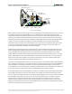
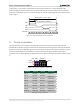
Current
waveform
through
horizontal
defletion
coil
Stable current ramp - information
is displayed during this time
Retrace - no
information
displayed
during this
time
Total horizontal time
Horizontal display time
Horizontal sync signal
sets retrace frequency
retrace
time
time
HS
"back porch""front porch"
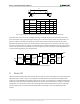
Display Surface
640 pixels per row are displayed
during forward beam trace
pixel 0,639
pixel 0,0
pixel 479,0 pixel 479,639
Figure 13. VGA horizontal synchronization.
Video data typically comes from a video refresh memory; with one or more bytes assigned to each pixel location
(the Basys 3 uses 12-bits per pixel). The controller must index into video memory as the beams move across the
display, and retrieve and apply video data to the display at precisely the time the electron beam is moving across a
given pixel.
A VGA controller circuit must generate the HS and VS timings signals and coordinate the delivery of video data
based on the pixel clock. The pixel clock defines the time available to display one pixel of information. The VS signal
defines the "refresh" frequency of the display, or the frequency at which all information on the display is redrawn.
The minimum refresh frequency is a function of the display's phosphor and electron beam intensity, with practical
refresh frequencies falling in the 50Hz to 120Hz range. The number of lines to be displayed at a given refresh
frequency defines the horizontal "retrace" frequency. For a 640-pixel by 480-row display using a 25 MHz pixel clock
and 60 +/-1Hz refresh, the signal timings shown in Fig. 14 can be derived. Timings for sync pulse width and front
and back porch intervals (porch intervals are the pre- and post-sync pulse times during which information cannot
be displayed) are based on observations taken from actual VGA displays.