
Datasheet


Basys 3™ FPGA Board Reference Manual
Copyright Digilent, Inc. All rights reserved.
Other product and company names mentioned may be trademarks of their respective owners.
Page 15 of 19
Artix-7
U16
E19
LD0
LD1
U19
V19
LD2
LD3
W18
U15
LD4
LD5
U14
V14
LD6
LD7
V13
V3
LD8
LD9
W3
U3
LD10
LD11
P3
N3
LD12
LD13
P1
L1
LD14
LD15
W7
W6
U8
V8
U5
V5
U7
CA
CB
CC
CD
CE
CF
CG
DP
V7
7-segment
Display
3.3V
AN3
AN2
AN1
AN0
W4
V4
U4
U2
T18
T17
W19
U17
BTNL
BTNR
BTNU
BTND
3.3V
Buttons
U18
BTNC
W16
W17
W15
V15
W14
W13
SW0
SW1
SW2
SW3
SW4
SW5
SW6
SW7
3.3V
V16
V17
T2
R3
W2
U1
T1
R2
SW8
SW9
SW10
SW11
SW14
SW12
SW13
SW15
T3
V2
Slide
Switches
LEDs
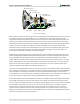
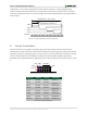
Figure 16. General purpose I/O devices on the Basys 3.
The sixteen individual high-efficiency LEDs are anode-connected to the FPGA via 330 ohm resistors, so they will
turn on when a logic high voltage is applied to their respective I/O pin. Additional LEDs, which are not user-
accessible, indicate power-on, FPGA programming status, and USB port status.
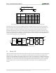
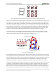
8.1 Seven-Segment Display
The Basys 3 board contains one four-digit common anode seven-segment LED display. Each of the four digits is
composed of seven segments arranged in a "figure 8" pattern, with an LED embedded in each segment. Segment
LEDs can be individually illuminated, so any one of 128 patterns can be displayed on a digit by illuminating certain
LED segments and leaving the others dark, as shown in Fig. 17. Of these 128 possible patterns, the ten
corresponding to the decimal digits are the most useful.