
Datasheet


Basys 3™ FPGA Board Reference Manual
Copyright Digilent, Inc. All rights reserved.
Other product and company names mentioned may be trademarks of their respective owners.
Page 16 of 19
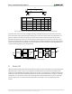
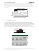
Figure 17. An un-illuminated seven-segment display and nine illumination patterns corresponding to decimal digits.
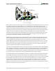
The anodes of the seven LEDs forming each digit are tied together into one "common anode" circuit node, but the
LED cathodes remain separate, as shown in Fig. 18. The common anode signals are available as four "digit enable"
input signals to the 4-digit display. The cathodes of similar segments on all four displays are connected into seven
circuit nodes labeled CA through CG (for example, the four "D" cathodes from the four digits are grouped together
into a single circuit node called "CD"). These seven cathode signals are available as inputs to the 4-digit display.
This signal connection scheme creates a multiplexed display, where the cathode signals are common to all digits
but they can only illuminate the segments of the digit whose corresponding anode signal is asserted.
To illuminate a segment, the anode should be driven high while the cathode is driven low. However, since the
Basys 3 uses transistors to drive enough current into the common anode point, the anode enables are inverted.
Therefore, both the AN0..3 and the CA..G/DP signals are driven low when active.
A
F
E
D
C
B
G
Common anode
Individual cathodes
DP
AN3 AN2 AN1 AN0
CA CB CC CD CE CF CG DP
Four-digit Seven
Segment Display
Figure 18. Common anode circuit node.
A scanning display controller circuit can be used to show a four-digit number on this display. This circuit drives the
anode signals and corresponding cathode patterns of each digit in a repeating, continuous succession at an update
rate that is faster than the human eye can detect. Each digit is illuminated just one-fourth of the time, but because
the eye cannot perceive the darkening of a digit before it is illuminated again, the digit appears continuously
illuminated. If the update, or "refresh", rate is slowed to around 45Hz, a flicker can be noticed in the display.
For each of the four digits to appear bright and continuously illuminated, all four digits should be driven once every
1 to 16ms, for a refresh frequency of about 1 KHz to 60Hz. For example, in a 62.5Hz refresh scheme, the entire
display would be refreshed once every 16ms, and each digit would be illuminated for 1/4 of the refresh cycle, or
4ms. The controller must drive the cathodes low with the correct pattern when the corresponding anode signal is
driven high. To illustrate the process, if AN0 is asserted while CB and CC are asserted, then a "1" will be displayed