
Datasheet


Basys 3™ FPGA Board Reference Manual
Copyright Digilent, Inc. All rights reserved.
Other product and company names mentioned may be trademarks of their respective owners.
Page 6 of 19
When the FPGA has been successfully configured, the behavior of the LED is application-specific. For example, if a
USB keyboard is plugged in, a rapid blink will signal the receipt of an HID input report from the keyboard.
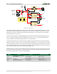
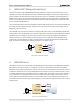
3 Memory
The Basys 3 board contains a 32Mbit non-volatile serial Flash device, which is attached to the Artix-7 FPGA using a
dedicated quad-mode (x4) SPI bus. The connections and pin assignments between the FPGA and the serial flash
device are shown in Fig. 4.
FPGA configuration files can be written to the Quad SPI Flash (Spansion part number S25FL032), and mode settings
are available to cause the FPGA to automatically read a configuration from this device at power on. An Artix-7 35T
configuration file requires just over two Mbytes of memory, leaving approximately 48% of the flash device
available for user data.
NOTE: Refer to the manufacturer's data sheets and the reference designs posted on Digilent's website for more
information about the memory devices.
CS#
SDI/DQ0
SDO/DQ1
C11
D19
D18
K19
SPI Flash
WP#/DQ2
HLD#/DQ3
G18
F18
SCK
Artix-7
SPI Flash
Figure 4. Basys 3 external memory.
4 Oscillators/Clocks
The Basys 3 board includes a single 100 MHz oscillator connected to pin W5 (W5 is a MRCC input on bank 34). The
input clock can drive MMCMs or PLLs to generate clocks of various frequencies and with known phase
relationships that may be needed throughout a design. Some rules restrict which MMCMs and PLLs may be driven
by the 100 MHz input clock. For a full description of these rules and of the capabilities of the Artix-7 clocking
resources, refer to the "7 Series FPGAs Clocking Resources User Guide" available from Xilinx.
Xilinx offers the LogiCORE™ Clocking Wizard IP to help users generate the different clocks required for a specific
design. This wizard properly instantiates the needed MMCMs and PLLs based on the desired frequencies and phase
relationships specified by the user. The wizard will then output an easy to use wrapper component around these
clocking resources that can be inserted into the user's design. The Clocking Wizard can be accessed from within IP
Catalog, which can be found under the Project Manager section of the Flow Navigator in Vivado.