
Datasheet
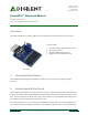

PmodAD2™ Reference Manual
Copyright Digilent, Inc. All rights reserved.
Other product and company names mentioned may be trademarks of their respective owners.
Page 2 of 2
digital conversions performed on them sequentially with the supply voltage VCC acting as the voltage reference for
the ADC.
After each conversion is performed, the device places itself into power-down mode. Upon a read command, the
device will wake itself up and prepare for a conversion, which takes approximately 0.6 μs. The actual conversion
process takes approximately 1.0 μs.
Pin
Signal
Description
1 & 5
SCL
Serial Clock
2 & 6
SDA
Serial Data
3 & 7
GND
Power Supply Ground
4 & 8
VCC
Power Supply (3.3V/5V)
Table 1. Pinout description table.
Any external power applied to the PmodAD2 must be within 2.7V and 5.5V; however, it is recommended that the
Pmod is operated at 3.3V.
3 Physical Dimensions
The pins on the pin header are spaced 100 mil apart. The PCB is 1 inch long on the sides parallel to the pins on the
pin header and 0.8 inches long on the sides perpendicular to the pin header.