
User Manual


Connecting TWI Interfaces
www.digilentinc.com
Copyright Digi
lent, Inc.
Page
3
of
5
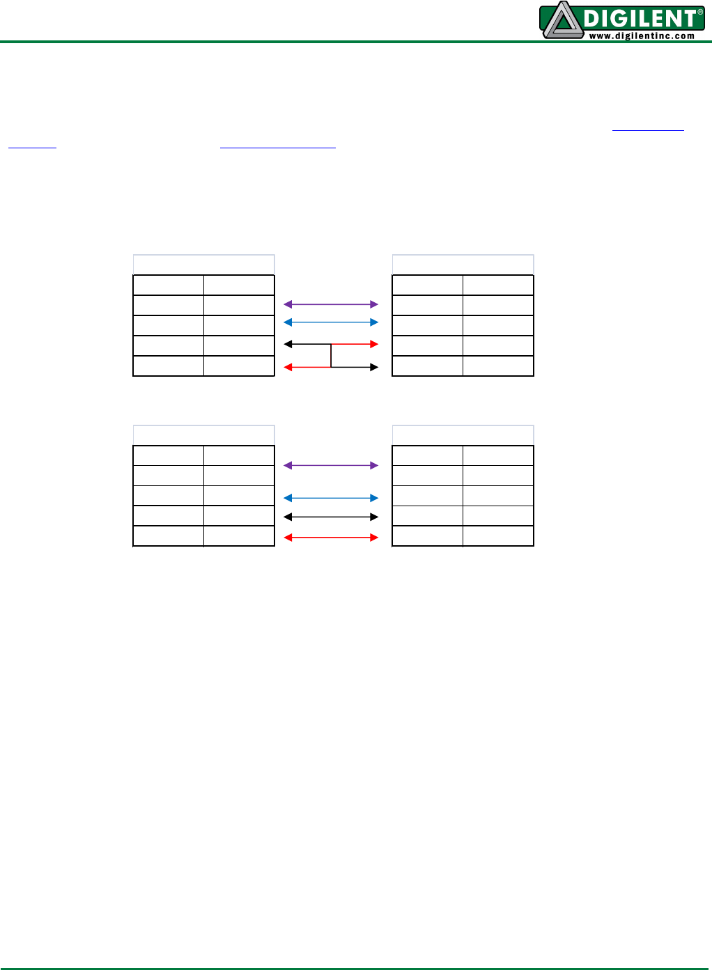
Connecting Configuration Type A:
To connect a type A device to another Type A device, or a Type B or Type C device, two 2 Pin MTE
Cables, a 4 Pin MTE Cable, or 6 Pin MTE Cable must be used. It is very important to ensure that
GND and VCC are connected to GND and VCC on both devices. Switching these wires may cause
damage to one or both devices. It may also be necessary to connect VCC and GND from another part
of the board, since not all Type A boards have VCC and GND pins located with the SCL and SDA
pins.
Pin Signal
varies SCL
varies SDA
varies GND
varies VCC
Type A
Pin Signal
1 or 2 SCL
3 or 4 SDA
5 or 6 VCC
7 or 8 GND
Type B
Pin Signal
1 or 2 SCL
3 or 4 SDA
5 or 6 GND
7 or 8 VCC
Type C
Pin Signal
varies SCL
varies SDA
varies GND
varies VCC
Type A