
User Manual


Connecting TWI Interfaces
www.digilentinc.com
Copyright Digi
lent, Inc.
Page
4
of
5
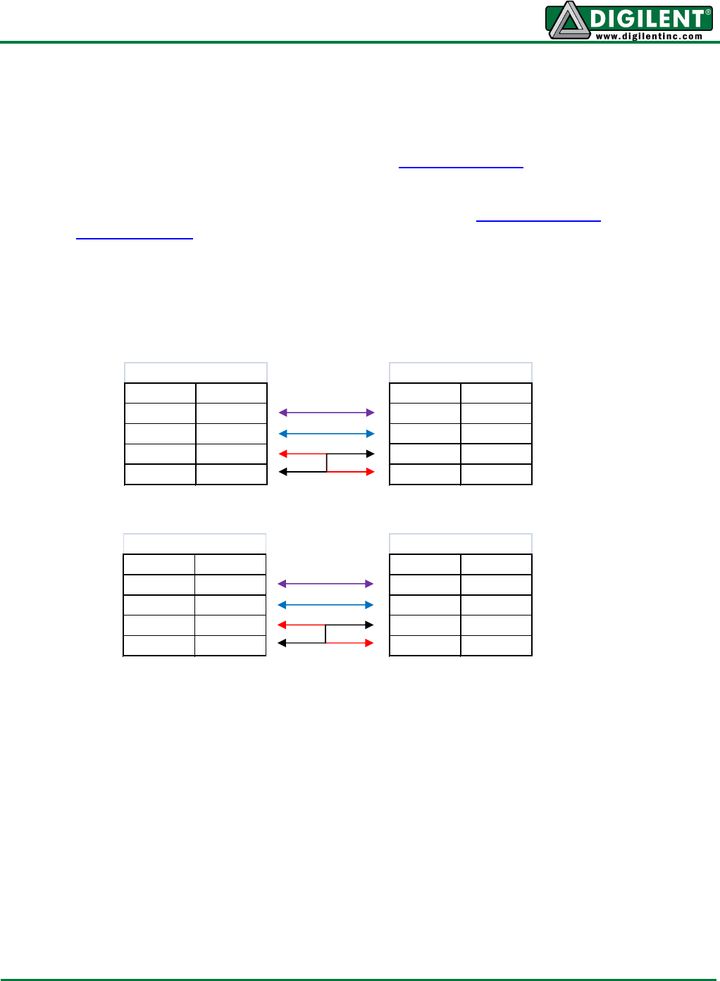
Connecting Configuration Type B:
Used for I
2
C connections over 2x4 pin headers.
Connection with another type B device requires only two 2 Pin MTE Cables or a 4 Pin MTE Cable,
taking care to match the colors of the wires to the same signal on both devices.
To connect a type B device to a type A device or type C device, two 2 Pin MTE Cables, a 4 Pin MTE
Cable, or 6 Pin MTE Cable must be used. It is very important to ensure that GND and VCC are
connected to GND and VCC on both devices. Switching these wires may cause damage to one or
both devices. It may also be the case that a Type A device does not have GND and VCC pins located
with the SCL and SDA pins. In these cases, it may be necessary to connect VCC and GND from
another part of the board.
Pin Signal
1 or 2 SCL
3 or 4 SDA
5 or 6 VCC
7 or 8 GND
Type B
Pin Signal
1 or 2 SCL
3 or 4 SDA
5 or 6 VCC
7 or 8 GND
Type B
Pin Signal
1 or 2 SCL
3 or 4 SDA
5 or 6 GND
7 or 8 VCC
Type C
Pin Signal
varies SCL
varies SDA
varies GND
varies VCC
Type A