
Manual


P
P
m
m
o
o
d
d
G
G
P
P
S
S
™
™
R
R
e
e
f
f
e
e
r
r
e
e
n
n
c
c
e
e
M
M
a
a
n
n
u
u
a
a
l
l
Revision: July 11, 2012
Note: This document applies to REV A of the board.
1300 NE Henley Court, Suite 3
Pullman, WA 99163
(509) 334 6306 Voice | (509) 334 6300 Fax
Doc: 502-237 page 1 of 4
Copyright Digilent, Inc. All rights reserved. Other product and company names mentioned may be trademarks of their respective owners.
Overview
The PmodGPS is an ideal solution for any
embedded system in need of satellite
positioning accuracy. It features the GlobalTop
Gms-u1LP GPS antenna module which utilizes
the MediaTek GPS MT3329.
Features include:
standard UART interface
input voltage: 3V – 3.6V
10Hz maximum update rate (1Hz
Default rate)
3m 2D accuracy without aid
super low power consumption (24mA
tracking and 30mA during acquisition)
ultra-high sensitivity: -165dBm
515m/s maximum velocity and 18,000m
maximum altitude
integrated ceramic GPS antenna
auto switchover to external antenna
12.5mm coin cell retainer for battery
backup of GPS RTCC and almanac
Functional Description
The Pmod GPS utilizes a standard 6-pin
connector and communicates via 2-wire UART.
Also available on the board is a 2-pin
connector for control of the NRST pin to the
module and also the RTCM pin for DGPS data
of RTCM protocol (this feature is disabled by
default, contact GlobalTop to enable).
Interface
The PmodGPS uses UART protocol for data
transmission and reception. By default, the
interface uses a baud rate of 9600, 8 data bits,
no parity, and a single stop bit. The module
provides the option for changing the baud rate
to predefined values which range from 4800 to
115,200.
The reset pin (NRST) on J2 is active low. If
the NRST pin is toggled, the device will
undergo a full reset. This reset performs
similarly to a power cycling of the device. The
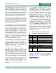
1PPS pin on J1 provides a one pulse-per-
second output which is synchronized to GPS
time. See the timing diagram in fig.1 for a
visual representation.
1PPS Timing Diagram
Figure 1 – 1PPS Pin
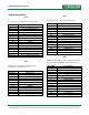
The 3DF pin on J1 indicates a positional fix. .
When the module has a fix (2D or 3D) this pin
is held low, if the module is unable to get a fix
then the pin will toggle every second as seen
below in the diagram. LD1 also follows this
same behavior pattern in order to give the user
a visual representation.
Figure 2 – 3DF Pin output without a fix