
Information
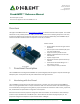


PmodAMP3™ Reference Manual
Copyright Digilent, Inc. All rights reserved.
Other product and company names mentioned may be trademarks of their respective owners.
Page 3 of 3
Any external power applied to the PmodAMP3 must be within 2.5V and 5.5V; however, it is recommended that the
Pmod is operated at 3.3V.
3 Physical Dimensions
The pins on the pin header are spaced 100 mil apart. The PCB is 1.5 inches long on the sides parallel to the pins on
the pin header and 0.8 inches long on the sides perpendicular to the pin header.
Header J2
Header J3
Header J4
Pin
Description
Pin
Description
Pin
Description
1
Left Audio
Jack
1
Serial Clock
1
Right Audio
Jack
2
Serial Data
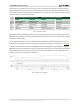
Header J1
Pin
Signal
Description
1
LRCLK
Left/Right Word Clock
2
SDATA
Serial Data
3
NC
Not Connected
4
BCLK
Bit Clock
5
GND
Power Supply Ground
6
VCC
Positive Power Supply
7
NC
Not Connected
8
NC
Not Connected
9
MCLK-E
Master Clock-external
10
~SHUT
Shutdown
11
GND
Power Supply Ground
12
VCC
Positive Power Supply
Table 2. Header J1 pinout table.
Table 3. Header J2, J3, and J4 pinout table.
Figure 2. PmodAMP3 block diagram.