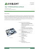
300 Henley Court Pullman, WA 99163 509.334.6306 www.digilentinc.com Arty™ FPGA Board Reference Manual Revised June 7, 2017 This manual applies to the Arty Rev. C Overview Arty is a ready-to-use development platform designed around the Artix-7 Field Programmable Gate Array (FPGA) from Xilinx. It was designed specifically for use as a MicroBlaze Soft Processing System.
Arty FPGA Board Reference Manual Arty is fully compatible with the high-performance Vivado ® Design Suite. It is supported under the free WebPACK™ license, so designs can be implemented at no additional cost. This free license includes the ability to create MicroBlaze™ soft-core processor designs. Design resources, example projects, and tutorials are available for download at the Arty Resource Center, accessible from reference.digilentinc.com.
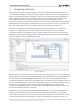
Arty FPGA Board Reference Manual 2 Designing with Arty What makes Arty so flexible is its FPGA. Among their many features, FPGAs have the ability to transform into a custom software-defined System-on-a-Chip (SoC). These “Soft SoC” FPGA configurations are designed graphically using a tool called Vivado IP Integrator (Vivado IPI). In this tool, pre-built peripheral blocks are dragged from an extensive library and dropped into your processing system as you see fit.
Arty FPGA Board Reference Manual instead is used by those familiar with FPGA design or interested in designing and implementing a digital circuit that doesn't contain a processor. Figure 2.2. Xilinx Software Development Kit (XSDK). 3 Power Supplies The Arty board requires a 5V power source to operate. This power source can come from the Digilent USB-JTAG port (J10) or it can be derived from a 7 to 15 Volt DC power supply that’s connected to Power Jack (J12) or Pin 8 of Header J7.
Arty FPGA Board Reference Manual The USB port can deliver enough power for the vast majority of designs. However, a few demanding applications, including any that drive multiple peripheral boards, might require more power than the USB port can provide. Also, some applications may need to run without being connected to a PC’s USB port. In these instances, an external power supply or battery pack can be used.
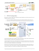
Arty FPGA Board Reference Manual wish to monitor the voltage of an external supply may configure Channel 2 of the XADC as a unipolar input and perform a conversion to receive a digital value corresponding to the input voltage. The figure below provides an overview that allows an external supply voltage to be monitored. Figure 3.1.1. Monitoring external voltage supply. 3.2 FPGA Core Supply Current Monitoring The Arty board includes circuitry for monitoring the current consumed by the FPGA core.
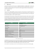
Arty FPGA Board Reference Manual Figure 3.3.1. 5V supply power consumption. 4 FPGA Configuration After power-on, the Artix-7 FPGA must be configured (or programmed) before it can perform any function. You can configure the FPGA in one of two ways: 1. 2. A PC can use the Digilent USB-JTAG circuitry (port J10) to program the FPGA any time the power is on. A file stored in the nonvolatile serial (SPI) flash device can be transferred to the FPGA using the SPI port. Figure 4.1. Arty configuration.
Arty FPGA Board Reference Manual An Artix-7 35T bitstream is typically 17,536,096 bits. The time it takes to program the Arty can be decreased by compressing the bitstream before programming, and then allowing the FPGA to decompress the bitstream itself during configuration. Depending on design complexity, compression ratios of 10x can be achieved. Bitstream compression can be enabled within the Xilinx tools (ISE or Vivado) to occur during generation.
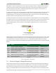
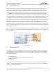
Arty FPGA Board Reference Manual 5 Memory The Arty board contains two external memories: a 256MB DDR3L SDRAM and a 128Mb (16MB) non-volatile serial flash device. The DDR3L module is connected to the FPGA using the industry standard interface. The serial flash is on a dedicated quad-mode (x4) SPI bus. The connection and a pin assignment between the FPGA and external memories are shown below. 5.
Arty FPGA Board Reference Manual 5.2 Quad-SPI Flash FPGA configuration files can be written to the Quad-SPI Flash (Micron part number N25Q128A13ESF40), and setting the mode jumper will cause the FPGA to automatically read a configuration from this device at power on. An Artix-7 35T configuration file requires 17,536,096 bits of memory, leaving about 87% of the flash device (or ~14MB) available for user data.
Arty FPGA Board Reference Manual Vivado IPI-based designs can access the PHY using either the AXI EthernetLite IP core, the AXI 1G/2.5G Ethernet Subsystem IP core, or the Tri Mode Ethernet MAC IP core. A 25 MHz clock needs to be generated for the X1 pin of the external PHY, labeled ETH_REF_CLK in the Arty Schematic. To learn how to properly use the Ethernet PHY in a MicroBlaze design on the Arty, refer to the Getting Started with MicroBlaze Servers tutorial from the Arty Resource Center.
Arty FPGA Board Reference Manual 8 USB-UART Bridge (Serial Port) The Arty includes an FTDI FT2232HQ USB-UART bridge (attached to connector J10) that allows you use PC applications to communicate with the board using standard Windows COM port commands. Free USB-COM port drivers, available from www.ftdichip.com under the “Virtual Com Port” or VCP heading, convert USB packets to UART/serial port data. Serial port data is exchanged with the FPGA using a two-wire serial port (TXD/RXD).
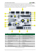
Arty FPGA Board Reference Manual general purpose push button. Note that it is also tied to the RST pin on J7 of the shield connector and to the FT2232 UART device via JP2, though these connections are not shown in the figure below. Figure 9.1. Arty GPIO. The four individual high-efficiency LEDs are anode-connected to the FPGA via 330-ohm resistors, so they will turn on when a logic high voltage is applied to their respective I/O pin.
Arty FPGA Board Reference Manual 10 Pmod Connectors Pmod connectors are 2×6, right-angle, 100-mil spaced female connectors that mate with standard 2×6 pin headers. Each 12-pin Pmod connector provides two 3.3V VCC signals (pins 6 and 12), two Ground signals (pins 5 and 11), and eight logic signals, as shown in Fig. 16.
Arty FPGA Board Reference Manual 10.2 High-speed Pmod The High-speed Pmods use the standard Pmod connector, but have their data signals routed as impedancematched differential pairs for maximum switching speeds. They have pads for loading resistors for added protection, but the Arty ships with these loaded as 0-ohm shunts. With the series resistors shunted, these Pmods offer no protection against short circuits, but allow for much faster switching speeds.
Arty FPGA Board Reference Manual Pin Name Shield Function Arty Connection IO0-IO13, IO26-IO41, A (IO42) General purpose I/O pins See Section titled “Shield Digital I/O” SCL I2C clock See Section titled “Shield Digital I/O” SDA I2C data See Section titled “Shield Digital I/O” SCLK SPI clock See Section titled “Shield Digital I/O” MOSI SPI data out See Section titled “Shield Digital I/O” MISO SPI data in See Section titled “Shield Digital I/O” SS SPI slave select See Section titled “Shi
Arty FPGA Board Reference Manual Absolute Minimum Voltage Recommended Minimum Operating Voltage Recommended Maximum Operating Voltage Absolute Maximum Voltage Powered -0.4V -0.2V 3.4V 3.75V Unpowered -0.4V N/A N/A 0.55V Table 6. Absolute maximum and recommended operating voltages. For more information on the electrical characteristics of the pins connected to the FPGA, please see the Artix-7 datasheet from Xilinx. 11.
Arty FPGA Board Reference Manual The pins labeled V_P and V_N are connected to the VP_0 and VN_0 dedicated analog inputs of the FPGA. This pair of pins can also be used as a differential analog input with voltage between 0-1V, but they cannot be used as Digital I/O. The capacitor in the circuit shown in Figure 11.2.2 for this pair of pins is loaded on the Arty. Figure 11.2.2. Dedicated analog inputs.