
Data Sheet


Arty FPGA Board Reference Manual
Copyright Digilent, Inc. All rights reserved.
Other product and company names mentioned may be trademarks of their respective owners.
Page 12 of 18
8 USB-UART Bridge (Serial Port)
The Arty includes an FTDI FT2232HQ USB-UART bridge (attached to connector J10) that allows you use PC
applications to communicate with the board using standard Windows COM port commands. Free USB-COM port
drivers, available from www.ftdichip.com under the “Virtual Com Port” or VCP heading, convert USB packets to
UART/serial port data. Serial port data is exchanged with the FPGA using a two-wire serial port (TXD/RXD). After
the drivers are installed, I/O commands can be used from the PC directed to the COM port to produce serial data
traffic on the A9 and D10 FPGA pins.
Two on-board status LEDs provide visual feedback on traffic flowing through the port: the transmit LED (LD10) and
the receive LED (LD9). Signal names that imply direction are from the point-of-view of the DTE (Data Terminal
Equipment), in this case the PC.
The FT2232HQ is also used as the controller for the Digilent USB-JTAG circuitry, but the USB-UART and USB-JTAG
functions behave entirely independent of one another. Programmers interested in using the UART functionality of
the FT2232 within their design do not need to worry about the JTAG circuitry interfering with the UART data
transfers, and vice-versa. The combination of these two features into a single device allows the Arty to be
programmed, communicated with via UART, and powered from a computer attached with a single Micro USB
cable.
The CK_RST signal (see the Arty Schematic) is also connected to the FT2232HQ device via JP2. When JP2 is shorted,
the FT2232HQ can trigger a MicroBlaze reset, mimicking the behavior of Arduino and chipKIT boards when
sketches are loaded. Note the CK_RST signal is also connected to the red RESET button and the RST pin of J7 on the
shield connector (these connections are not shown in the figure below).
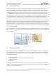
The connections between the FT2232HQ and the Artix-7 are shown in Figure 6.
Figure 8.1. UART.
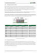
9 Basic I/O
The Arty board includes four tri-color LEDs, 4 switches, 4 push buttons, 4 individual LEDs, and a reset button, as
shown in Figure 16. The push buttons and slide switches are connected to the FPGA via series resistors to prevent
damage from inadvertent short circuits (a short circuit could occur if an FPGA pin assigned to a push button or slide
switch was inadvertently defined as an output). The four push buttons are “momentary” switches that normally
generate a low output when they are at rest, and a high output only when they are pressed. Slide switches
generate constant high or low inputs depending on their position.
The red reset button labeled “RESET” generates a high output when at rest and a low output when pressed. The
RESET button is intended to be used in MicroBlaze designs to reset the processor, but you can also use it as a