
Data Sheet


Arty FPGA Board Reference Manual
Copyright Digilent, Inc. All rights reserved.
Other product and company names mentioned may be trademarks of their respective owners.
Page 15 of 18
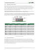
10.2 High-speed Pmod
The High-speed Pmods use the standard Pmod connector, but have their data signals routed as impedance-
matched differential pairs for maximum switching speeds. They have pads for loading resistors for added
protection, but the Arty ships with these loaded as 0-ohm shunts. With the series resistors shunted, these Pmods
offer no protection against short circuits, but allow for much faster switching speeds. The signals are paired to the
adjacent signals in the same row: pins 1 and 2, pins 3 and 4, pins 7 and 8, and pins 9 and 10.
Traces are routed 100 ohm (+/- 10%) differential.
These connectors should be used only when high speed differential signaling is required or the other Pmods are all
occupied. If used as single-ended, coupled pairs may have significant crosstalk. In applications where this is a
concern, the standard Pmod connector shall be used. Another option would be to ground one of the signals (drive
it low from the FPGA) and use its pair for the signal-ended signal.
Since the High-Speed Pmods have 0-ohm shunts instead of protection resistors, the operator must take precaution
to ensure that they do not cause any shorts.
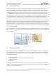
11 Arduino/chipKIT Shield Connector
Arty can be connected to standard Arduino and chipKIT shields to add extended functionality. Special care was
taken while designing Arty to make sure it is compatible with the majority of Arduino and chipKIT shields on the
market. The shield connector has 49 pins connected to the FPGA for general purpose Digital I/O. Due to the
flexibility of FPGAs, it is possible to use these pins for just about anything including digital read/write, SPI
connections, UART connections, I2C connections, and PWM. Six of these pins (labeled AN0-AN5) can also be used
as single-ended analog inputs with an input range of 0V-3.3V, and another six (labeled AN6-11) can be used as
differential analog inputs.
Note: The Arty is not compatible with shields that output 5V digital or analog signals. Driving pins on the Arty
shield connector above 5V may cause damage to the FPGA.
The figure below diagrams the pins found on the shield connector of the Arty.
Figure 11.1. Shield connector pin diagram.