
Data Sheet


Arty FPGA Board Reference Manual
Copyright Digilent, Inc. All rights reserved.
Other product and company names mentioned may be trademarks of their respective owners.
Page 4 of 18
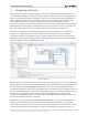
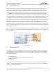
instead is used by those familiar with FPGA design or interested in designing and implementing a digital circuit that
doesn't contain a processor.
Figure 2.2. Xilinx Software Development Kit (XSDK).
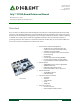
3 Power Supplies
The Arty board requires a 5V power source to operate. This power source can come from the Digilent USB-JTAG
port (J10) or it can be derived from a 7 to 15 Volt DC power supply that’s connected to Power Jack (J12) or Pin 8 of
Header J7. Header J13, located between the power jack and the Ethernet connector, is used to determine which
source is used.
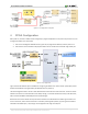
A power-good LED (LD11), driven by the “power good” (PWRGD) output of the ADP5052 regulator, indicates that
the board is receiving power and that the onboard supplies are functioning as expected. An overview of the Arty
power circuit is shown below.
Figure 3.1. Arty power circuit.