
Information


D
D
i
i
g
g
i
i
l
l
e
e
n
n
t
t
P
P
m
m
o
o
d
d
™
™
I
I
n
n
t
t
e
e
r
r
f
f
a
a
c
c
e
e
S
S
p
p
e
e
c
c
i
i
f
f
i
i
c
c
a
a
t
t
i
i
o
o
n
n
Revision: November 20, 2011
1300 NE Henley Court, Suite 3
Pullman, WA 99163
(509) 334 6306 Voice | (509) 334 6300 Fax
Doc: 510-002 page 1 of 11
Copyright Digilent, Inc. All rights reserved. Other product and company names mentioned may be trademarks of their respective owners.
Introduction
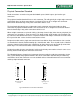
The Digilent Pmod interface is used to connect low frequency, low I/O pin count peripheral modules to
host controller boards. There are six-pin and twelve-pin versions of the interface defined. The six-pin
version provides four digital I/O signal pins, one power pin and one ground pin. The twelve-pin version
provides eight I/O signal pins, two power pins and two ground pins. The signals of the twelve-pin
version are arranged so that it provides two of the six-pin interfaces stacked.
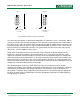
In general, Pmod peripheral modules can plug directly into connectors on the host controller board, or
be connected to the controller board via six-pin or twelve-pin cables. Two six-pin peripheral modules
can be connected to a single twelve-pin host connector via a twelve-pin to dual six-pin splitter cable.
Similarly, a single twelve-pin peripheral module can be connected to two six-pin host connectors via
the same twelve-pin to dual six-pin splitter cable.
Pmod peripheral modules are powered by the host via the interface’s power and ground pins.
The Pmod interface is not intended for high frequency operation, however, using RJ45 connectors
and twisted pair Ethernet cable, signals have been sent reliably at 24Mhz and distances of up to 4
meters.
In addition to the six and twelve pin interfaces, the Pmod peripheral module interface also
encompasses a variant using the I
2
C interface, and two or four wire MTE cables. In some cases, an
I
2
C connected module can be connected directly to a Pmod connector on a system board, but
generally the connection will be via MTE cables. The Pmod I
2
C interface provides the two I
2
C signals,
SDA and SCL, plus power and ground.
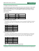
Electrical Specifications
The digital signal characteristics are not specified. However, the general expectation is that a 3.3V
logic power supply will be used and the signals will conform to LVCMOS 3.3V or LVTTL 3.3V logic
conventions.
The driver current source/sink capability isn’t specified and depends on the capabilities of the specific
system board or module. The I/O pins on the system board are generally directly driven by the FPGA
or microcontroller. The I/O pins on Xilinx FPGAs generally have symmetrical 24mA source/sink
capability. The drive capability of microcontrollers is generally less and some of them are not
symmetrical. The drive strength for microcontroller pins is generally in the range +/-5mA to +/-10mA.
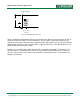
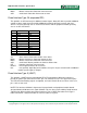
The I/O pins on system board Pmod connectors generally have ESD protection diodes and 200ohm
series resistors. The resistors are to limit short circuit currents if pins are inadvertently shorted, or to
protect against driver conflicts if outputs are inadvertently connected together.
Peripheral modules may be connected to the host via cables of up to 18” in length. The drivers on the
host or peripheral module should have sufficient drive strength to drive this length of cable at