
Information


Digilent Pmod™ Interface Specification
www.digilentinc.com page 2 of 11
Copyright Digilent, Inc. All rights reserved. Other product and company names mentioned may be trademarks of their respective owners.
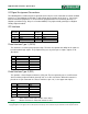
whatever the operating speed of the interface on the Pmod is expected to be. In general, this means
that the driver should be able to source or sink at least 5mA of current.
Peripheral modules may not assume that pull-up or pull-down resistors are present on the host and
must provide for proper termination of inputs, if necessary, and may not use open drain or open
collector outputs, unless the pull-up is provided on the peripheral module itself.
For I
2
C connected modules, the digital signal characteristics conform to the I
2
C specification. Either
5V or 3.3V levels can be used on most modules, but Digilent system boards operate at 3.3V, and the
modules are primarily intended for operation at 3.3V
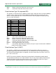
The driver current sink capability isn’t specified and depends on the capabilities of the specific system
board or module. The I/O pins on the system board are generally directly driven by the FPGA or
microcontroller. The I/O pins on Xilinx FPGAs generally have symmetrical 24mA source/sink
capability. The drive capability of microcontrollers is generally less and some of them are not
symmetrical.
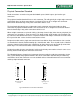
The I
2
C bus is an open collector bus. The pull-up resistors used to provide the logic high level are not
provided on the modules and therefore must be provided on the system board. Some Digilent system
boards use current mirrors rather than simple pull-up resistors to provide the logic high level to allow
driving longer busses with greater capacitive load.
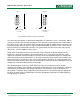
Microcontroller system boards are generally provided with dedicated I
2
C connectors and provide pull-
up resistors that are jumper selectable to be in or out of circuit. FPGA based system boards generally
do not provide dedicated I
2
C connectors, and depend on the internal pull-up resistors in the FPGA I/O
blocks to provide the pull-ups.
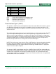
Power Supply
The power pins of the interface provide power from the host to the peripheral. The complete interface
requires that the host provide the ability to switch the voltage on the power pins between 5.0V and
3.3V. A reduced functionality subset of the spec. allows the host to provide only 3.3V at the power
supply pins, with no ability to switch. On the twelve-pin version of the interface, both power supply
pins switch together and always supply the same voltage. These pins may be shorted together at
either the host end or the peripheral end.
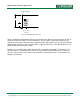
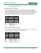
On I
2
C connected modules, the power pins of the interface provide power from the system board to
the peripheral module. The supplied voltage will generally be 3.3V, but operation at 5V is supported
by some modules. The connector on the modules provides two sets of the I2C signals and the power
and ground pins to allow daisy chaining multiple modules onto the bus. The two power pins and the
two ground pins may be shorted together respectively at either the system board end or the peripheral
module end of the connection.
The amount of power a peripheral module is allowed to draw from the host is not specified, but should
not be assumed to be more than approximately 100mA.