
Information


Digilent Pmod™ Interface Specification
www.digilentinc.com page 3 of 11
Copyright Digilent, Inc. All rights reserved. Other product and company names mentioned may be trademarks of their respective owners.
Physical Connection Standard
Pmod connections are made using standard 100mil spaced, 25mil square, pin-header style
connectors.
The peripheral module board will have a male connector. This will typically be a right angle connector,
at the board edge, for direct connection to a host board, This can be a straight male connector
inboard from the board edge if only cable connections will be used.
The host board will typically have a right angle female connector at the board edge for direct
connection of peripheral module boards. This connector can be a straight male connector inboard
from the board edge if only cable connections will be used.
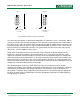
When multiple connectors are placed side-by-side along a board edge (either host or peripheral), the
connectors are spaced 0.9”, center-to-center. This allows for 0.8” wide modules to be plugged side-
by-side into a host without interference. Peripheral modules with multiple connectors must also have
them spaced on 0.9” centers for direct connection to a host.
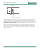
Peripheral modules with a single connector that are intended for direct connection to a host, or that
are intended to fit into the Pmod mounting clip, should be 0.8” wide. There should also be >25mil of
clearance from the board edge to any components to allow clearance for the Pmod clip to latch the
board edge. The connector should be centered along the 0.8” side of the module.
Peripheral modules that are more than 0.8” wide can be directly connected to a host in some cases
but may interfere with adjacent connectors on the host.
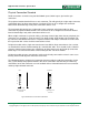
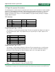
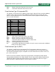
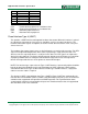
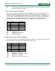
The following diagrams show physical connector placement and pin numbering conventions for the
host (system board) and peripheral module sides of the connection. Note that the pin numbering
conventions for the 2x6 connectors are non-standard and are mirrored between the host connector
and the peripheral board connector.
Host Peripheral
1
2
3
4
5
6
0.40"
1
2
3
4
5
6
0.15"
Right angle female
connector
Right angle male
connector
Fig 1: Standard Six-Pin Connector Placement