
Information


Digilent Pmod™ Interface Specification
www.digilentinc.com page 5 of 11
Copyright Digilent, Inc. All rights reserved. Other product and company names mentioned may be trademarks of their respective owners.
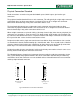
I
2
C Module PCB
1
3
5
7
0.20"
Right angle male
connector
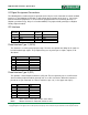
Fig 3: Standard Module Dimensions
2
4
6
8
0.80"
0.30"
Some early Digilent microcontroller based system boards have different connector layouts for the I
2
C
connectors. Some have two sets of 2x2 connectors, one for signals, and the other for power and
ground. One board has a 2x4 connector, but with the power and grounds reversed. All system boards
going forward should use a 2x4 connector with the signal assignments as described below in the I/O
Signal Assignment Conventions section.
Digilent has 2-wire MTE cables and a four wire cable specifically intended for I
2
C connections. The
four wire cable has a 4-position MTE shell on one end and two 2-position MTE shells on the other
end. This cable can be used to connect any Pmod with a standard (four wire) I
2
C connector to any
Digilent system board.