
Information


Digilent Pmod™ Interface Specification
www.digilentinc.com page 6 of 11
Copyright Digilent, Inc. All rights reserved. Other product and company names mentioned may be trademarks of their respective owners.
I/O Signal Assignment Conventions
The following define standard signal assignments to the I/O pins on the connector for certain standard
interfaces. In the following, the direction is defined from the perspective of the host: i.e. ‘Out’ means
from the host to the peripheral; ‘In’ means from the peripheral to the host. Generally the host is a
Digilent system board (e.g. Nexys II or Cerebot 32MX4). The peripheral will generally be a Digilent
Pmod peripheral module.
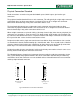
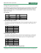
I2C Interface
Pin
Number
Signal Pin
Number
Signal
1 SCL 2 SCL
3 SDA 4 SDA
5 GND 6 GND
7 VCC 8 VCC
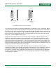
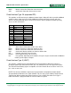
Pmod Interface Type 1 (GPIO)
This interface is used for general purpose logic. The host must provide the ability for all signals to
be bi-directional logic signals. The peripheral may use any of the pins as inputs, outputs, or bi-
directional.
Pin Signal Direction
1 IO1 In/Out
2 IO2 In/Out
3 IO3 In/Out
4 IO4 In/Out
5 GND
6 VCC
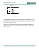
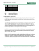
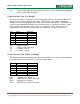
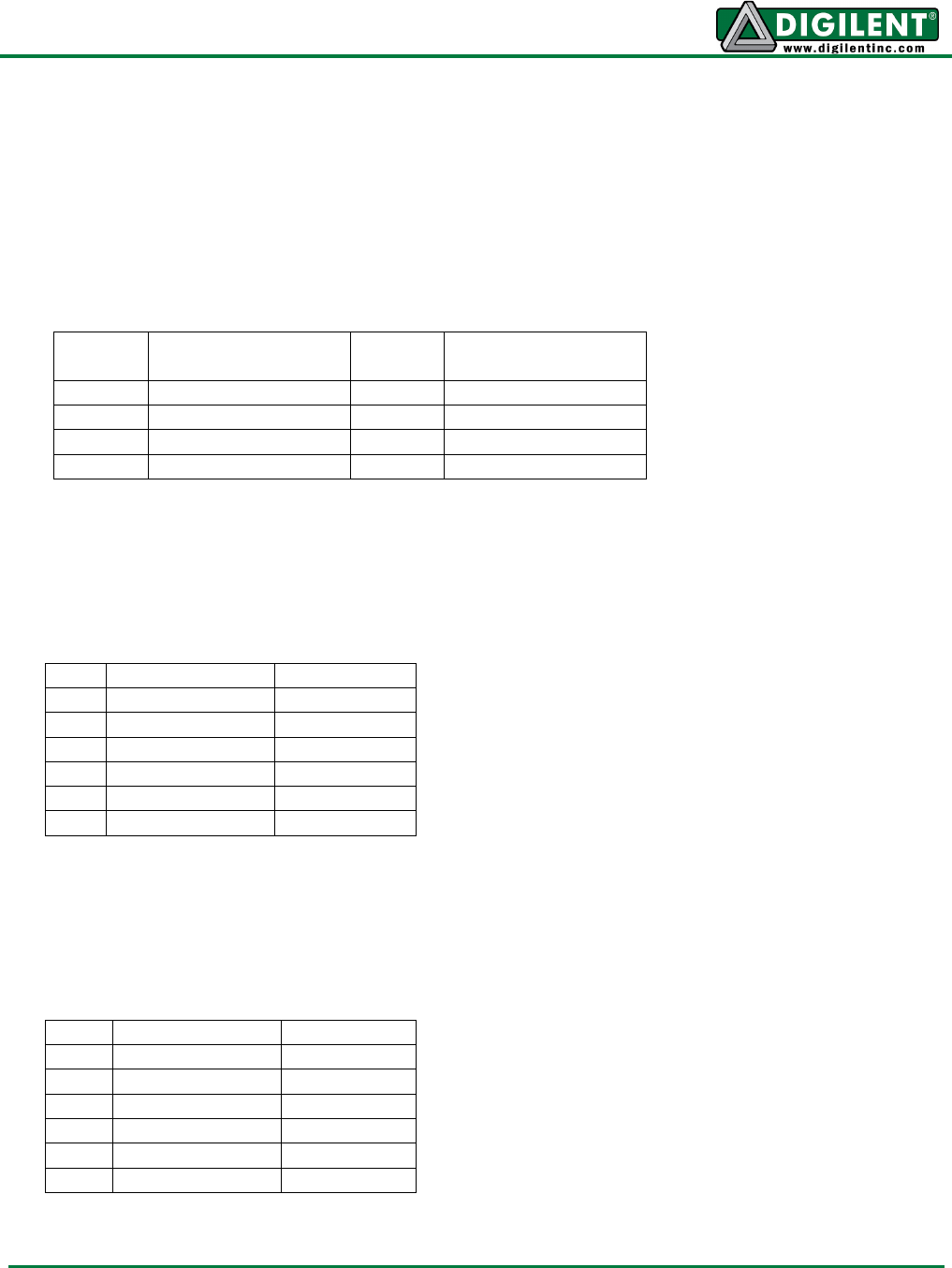
Pmod Interface Type 2 (SPI)
This provides a Serial Peripheral Interface (SPI) port. The host generally acts as an SPI master
device and the peripheral module generally acts as an SPI slave device. When this interface is
placed on a 12-pin connector on a host, it should use pins 1-6 (i.e. the upper row of pins).
Pin Signal Direction
1 SS Out
2 MOSI Out
3 MISO In
4 SCK Out
5 GND
6 VCC
SS - Slave Select. Active low to enable slave device
MOSI - Master Out Slave In. Data from master to slave