
Information


Digilent Pmod™ Interface Specification
www.digilentinc.com page 7 of 11
Copyright Digilent, Inc. All rights reserved. Other product and company names mentioned may be trademarks of their respective owners.
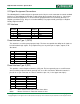
MISO - Master In Slave Out. Data from slave to master
SCK - Serial clock. Data clock from master to slave
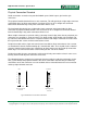
Pmod Interface Type 2A (expanded SPI)
This provides an SPI interface plus additional control signals. Many SPI devices provide additional
control or status signals that can provide additional functions between the master and slave
devices. The host generally acts as an SPI master device and the peripheral module generally
acts as an SPI slave device.
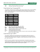
Pin Signal Direction
1 SS Out
2 MOSI Out
3 MISO In
4 SCK Out
5 GND
6 VCC
7 INT In
8 RESET Out
9 N/S N/S
10 N/S N/S
11 GND
12 VCC
SS - Slave Select. Active low to enable slave device
MOSI - Master Out Slave In. Data from master to slave
MISO - Master In Slave Out. Data from slave to master
SCK - Serial clock. Master provides the clock to shift the data
INT - Interrupt signal from slave to master
RESET - Reset signal for master to reset slave
N/S - not-specified, depending on the module, these pins may be unconnected or additional
module specific inputs or outputs.
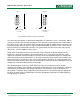
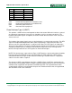
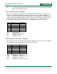
Pmod Interface Type 3 (UART)
This provides a UART interface with optional RTS/CTS handshaking. When this interface is
placed on a twelve-pin connector on a host, pins 1-6 should be used (i.e. the upper row of pins).
The RTS/CTS handshaking signals are optional, and some Pmods do not use them. In this case,
pins 1 & 2 are not used.
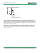
NOTE: This interface definition is deprecated. System boards and peripheral module boards
designed before 07/2010 use this signal definition. This has been superseded by Pmod Interface
Type 4 below. When making connections between a Type 3 UART connection and a Type 4
UART connection, a flying lead cable or crossover cable is required.