
User manual
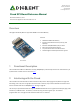

Pmod SF3 Reference Manual
Copyright Digilent, Inc. All rights reserved.
Other product and company names mentioned may be trademarks of their respective owners.
Page 2 of 2
Users that wish to simply use the memory module without concerning themselves with the dual/quad input and
output communication may use the example code and tutorials found on the Pmod SF3 Resource Center.
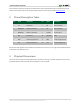
3 Pinout Description Table
Pin
Signal
Description
Pin
Signal
Description
1
~CS
Chip Select
7
NC
Not Connected
2
MOSI/DQ0
Master-Out-Slave-In
8
NC
Not Connected
3
MISO/DQ1
Master-In-Slave-Out
9
W/DQ2
Write Protect
4
SCK
Serial Clock
10
HLD/DQ3
Hold
5
GND
Power Supply Ground
11
GND
Power Supply Ground
6
VCC
Power Supply (3.3V)
12
VCC
Power Supply (3.3V)
Any external power applied to the Pmod SF3 must be within 2.31V and 3.7V; it is strongly recommended the Pmod
is operated at 3.3V. Bottom of Form
4 Physical Dimensions
The pins on the pin header are spaced 100 mil apart. The PCB is 1 inch long on the sides parallel to the pins on the
pin header and 0.8 inches long on the sides perpendicular to the pin header.