
User manual


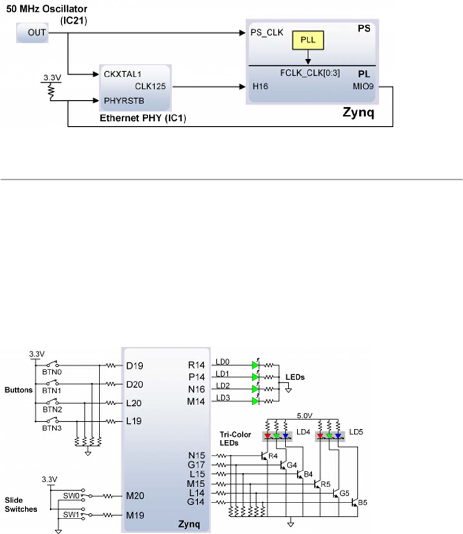
Figure 11.1. Arty Z7 clocking.
12 Basic I/O
The Arty Z7 board includes two tri-color LEDs, 2 switches, 4 push buttons, and 4 individual
LEDs as shown in Figure 12.1. The push buttons and slide switches are connected to the Zynq
PL via series resistors to prevent damage from inadvertent short circuits (a short circuit could
occur if an FPGA pin assigned to a push button or slide switch was inadvertently defined as an
output). The four push buttons are “momentary” switches that normally generate a low output
when they are at rest, and a high output only when they are pressed. Slide switches generate
constant high or low inputs depending on their position.
Figure 12.1. Arty Z7 GPIO.
The four individual high-efficiency LEDs are anode-connected to the Zynq PL via 330-ohm
resistors, so they will turn on when a logic high voltage is applied to their respective I/O pin.
Additional LEDs that are not user-accessible indicate power-on, PL programming status, and
USB and Ethernet port status.