
User manual


The SRST button also causes the CK_RST signal to toggle in order to trigger a reset on any
attached shields.
15 Pmod Ports
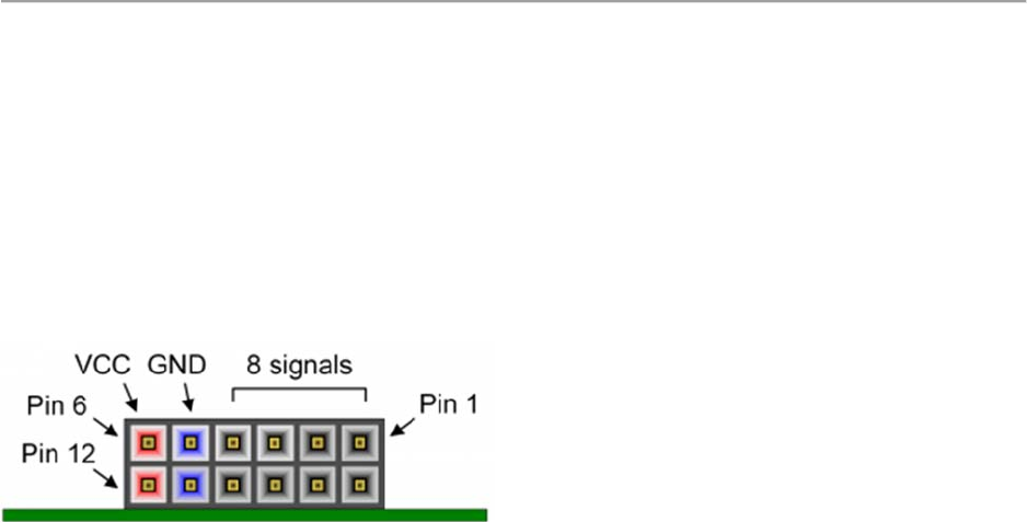
Pmod ports are 2×6, right-angle, 100-mil spaced female connectors that mate with standard 2×6
pin headers. Each 12-pin Pmod port provides two 3.3V VCC signals (pins 6 and 12), two Ground
signals (pins 5 and 11), and eight logic signals, as shown in Figure 15.1. The VCC and Ground
pins can deliver up to 1A of current, but care must be taken not to exceed any of the power
budgets of the onboard regulators or the external power supply (see the 3.3V rail current limits
listed in the “Power Supplies” section).
Figure 15.1. Pmod Port Diagram
Digilent produces a large collection of Pmod accessory boards that can attach to the Pmod
expansion connectors to add ready-made functions like A/D’s, D/A’s, motor drivers, sensors, and
other functions. See www.digilentinc.com for more information.
Each Pmod port found on Digilent FPGA boards falls into one of four categories: standard, MIO
connected, XADC, or high-speed. The Arty Z7 has two Pmod ports, both of which are the high-
speed type. The following section describes the high-speed type of Pmod port.
15.1 High-Speed Pmods
The High-speed Pmods have their data signals routed as impedance matched differential pairs for
maximum switching speeds. They have pads for loading resistors for added protection, but the
Arty Z7 ships with these loaded as 0-Ohm shunts. With the series resistors shunted, these Pmods
offer no protection against short circuits, but allow for much faster switching speeds. The signals
are paired to the adjacent signals in the same row: pins 1 and 2, pins 3 and 4, pins 7 and 8, and
pins 9 and 10.
Traces are routed 100 ohm (+/- 10%) differential.
If pins on this port are used as single-ended signals, coupled pairs may exhibit crosstalk. In
applications where this is a concern, one of the signals should be grounded (drive it low from the
FPGA) and use its pair for the signal-ended signal.