
User manual


Stage 1
During this stage, the FSBL first finishes configuring the PS components, such as the DDR
memory controller. Then, if a bitstream is present in the Zynq Boot Image, it is read and used to
configure the PL. Finally, the user application is loaded into memory from the Zynq Boot Image,
and execution is handed off to it.
Stage 2
The last stage is the execution of the user application that was loaded by the FSBL. This can be
any sort of program, from a simple “Hello World” design, to a Second Stage Boot loader used to
boot an operating system like Linux. For a more thorough explanation of the boot process, refer
to Chapter 6 of the Zynq Technical Reference manual.
The Zynq Boot Image is created using Vivado and Xilinx Software Development Kit (Xilinx
SDK). For information on creating this image please refer to the available Xilinx documentation
for these tools.
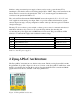
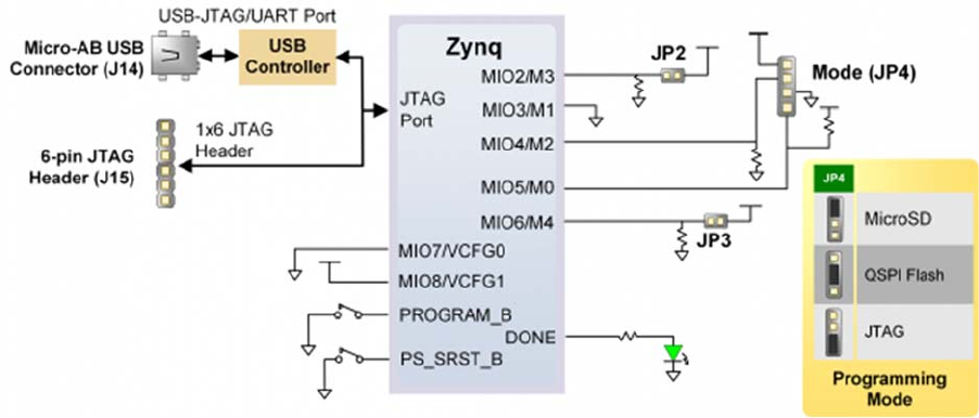
The Arty Z7 supports three different boot modes: microSD, Quad SPI Flash, and JTAG. The
boot mode is selected using the Mode jumper (JP4), which affects the state of the Zynq
configuration pins after power-on. Figure 3.1 depicts how the Zynq configuration pins are
connected on the Arty Z7.
Figure 3.1. Arty Z7 configuration pins.