
User manual


Table Of Contents
- Zynq-7000 All Programmable SoC
- Table of Contents
- Ch. 1: Introduction
- Ch. 2: Signals, Interfaces, and Pins
- Ch. 3: Application Processing Unit
- Ch. 4: System Addresses
- Ch. 5: Interconnect
- Ch. 6: Boot and Configuration
- Ch. 7: Interrupts
- Ch. 8: Timers
- Ch. 9: DMA Controller
- Introduction
- Functional Description
- DMA Transfers on the AXI Interconnect
- AXI Transaction Considerations
- DMA Manager
- Multi-channel Data FIFO (MFIFO)
- Memory-to-Memory Transfers
- PL Peripheral AXI Transactions
- PL Peripheral Request Interface
- PL Peripheral - Length Managed by PL Peripheral
- PL Peripheral - Length Managed by DMAC
- Events and Interrupts
- Aborts
- Security
- IP Configuration Options
- Programming Guide for DMA Controller
- Programming Guide for DMA Engine
- Programming Restrictions
- System Functions
- I/O Interface
- Ch. 10: DDR Memory Controller
- Introduction
- AXI Memory Port Interface (DDRI)
- DDR Core and Transaction Scheduler (DDRC)
- DDRC Arbitration
- Controller PHY (DDRP)
- Initialization and Calibration
- DDR Clock Initialization
- DDR IOB Impedance Calibration
- DDR IOB Configuration
- DDR Controller Register Programming
- DRAM Reset and Initialization
- DRAM Input Impedance (ODT) Calibration
- DRAM Output Impedance (RON) Calibration
- DRAM Training
- Write Data Eye Adjustment
- Alternatives to Automatic DRAM Training
- DRAM Write Latency Restriction
- Register Overview
- Error Correction Code (ECC)
- Programming Model
- Ch. 11: Static Memory Controller
- Ch. 12: Quad-SPI Flash Controller
- Ch. 13: SD/SDIO Controller
- Ch. 14: General Purpose I/O (GPIO)
- Ch. 15: USB Host, Device, and OTG Controller
- Introduction
- Functional Description
- Programming Overview and Reference
- Device Mode Control
- Device Endpoint Data Structures
- Device Endpoint Packet Operational Model
- Device Endpoint Descriptor Reference
- Programming Guide for Device Controller
- Programming Guide for Device Endpoint Data Structures
- Host Mode Data Structures
- EHCI Implementation
- Host Data Structures Reference
- Programming Guide for Host Controller
- OTG Description and Reference
- System Functions
- I/O Interfaces
- Ch. 16: Gigabit Ethernet Controller
- Ch. 17: SPI Controller
- Ch. 18: CAN Controller
- Ch. 19: UART Controller
- Ch. 20: I2C Controller
- Ch. 21: Programmable Logic Description
- Ch. 22: Programmable Logic Design Guide
- Ch. 23: Programmable Logic Test and Debug
- Ch. 24: Power Management
- Ch. 25: Clocks
- Ch. 26: Reset System
- Ch. 27: JTAG and DAP Subsystem
- Ch. 28: System Test and Debug
- Ch. 29: On-Chip Memory (OCM)
- Ch. 30: XADC Interface
- Ch. 31: PCI Express
- Ch. 32: Device Secure Boot
- Appx. A: Additional Resources
- Appx. B: Register Details
- Overview
- Acronyms
- Module Summary
- AXI_HP Interface (AFI) (axi_hp)
- CAN Controller (can)
- DDR Memory Controller (ddrc)
- CoreSight Cross Trigger Interface (cti)
- Performance Monitor Unit (cortexa9_pmu)
- CoreSight Program Trace Macrocell (ptm)
- Debug Access Port (dap)
- CoreSight Embedded Trace Buffer (etb)
- PL Fabric Trace Monitor (ftm)
- CoreSight Trace Funnel (funnel)
- CoreSight Intstrumentation Trace Macrocell (itm)
- CoreSight Trace Packet Output (tpiu)
- Device Configuration Interface (devcfg)
- DMA Controller (dmac)
- Gigabit Ethernet Controller (GEM)
- General Purpose I/O (gpio)
- Interconnect QoS (qos301)
- NIC301 Address Region Control (nic301_addr_region_ctrl_registers)
- I2C Controller (IIC)
- L2 Cache (L2Cpl310)
- Application Processing Unit (mpcore)
- On-Chip Memory (ocm)
- Quad-SPI Flash Controller (qspi)
- SD Controller (sdio)
- System Level Control Registers (slcr)
- Static Memory Controller (pl353)
- SPI Controller (SPI)
- System Watchdog Timer (swdt)
- Triple Timer Counter (ttc)
- UART Controller (UART)
- USB Controller (usb)
Zynq-7000 AP SoC Technical Reference Manual www.xilinx.com 1811
UG585 (v1.11) September 27, 2016
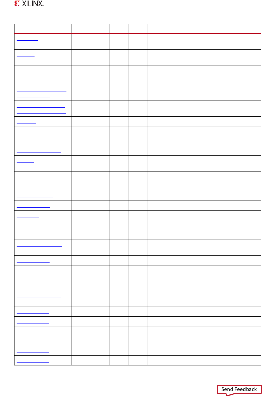
Appendix B: Register Details
USBCMD 0x00000140 24 mixed 0x00080000 USB Commands (EHCI
extended)
USBSTS
0x00000144 26 mixed 0x00000000 Interrupt/Raw Status (EHCI
extended) (Host/Device)
USBINTR
0x00000148 26 mixed 0x00000000 Interrrupts and Enables
FRINDEX
0x0000014C 14 rw 0x00000000 Frame List Index
PERIODICLISTBASE_
DEVICEADDR
0x00000154 32 mixed 0x00000000 Host/Device Address dual-use
ASYNCLISTADDR_E
NDPOINTLISTADDR
0x00000158 32 mixed 0x00000000 Host/Device dual-use
TTCTRL
0x0000015C 32 mixed 0x00000000 TT Control
BURSTSIZE
0x00000160 17 rw 0x00001010 Burst Size
TXFILLTUNING
0x00000164 22 mixed 0x00000000 TxFIFO Fill Tuning
TXTTFILLTUNING
0x00000168 13 mixed 0x00000000 TT TX latency FIFO
IC_USB
0x0000016C 32 mixed 0x00000000 Low and Fast Speed Control
constants
ULPI_VIEWPORT
0x00000170 32 mixed 0x08000000 ULPI Viewport
ENDPTNAK
0x00000178 32 wtc 0x00000000 Endpoint NAK (Device mode)
ENDPTNAKEN
0x0000017C 32 rw 0x00000000 Endpoint NAK (Device mode)
CONFIGFLAG
0x00000180 32 ro 0x00000001 reserved
PORTSC1
0x00000184 32 mixed 0x8C000004 Port Status & Control
OTGSC
0x000001A4 32 mixed 0x00001020 OTG Status and Control
USBMODE
0x000001A8 32 mixed 0x00000000 USB Mode Selection
ENDPTSETUPSTAT
0x000001AC 16 wtc 0x00000000 Endpoint Status Setup (Device
mode)
ENDPTPRIME
0x000001B0 32 wtc 0x00000000 Endpoint Primer (Device mode)
ENDPTFLUSH
0x000001B4 32 wtc 0x00000000 Endpoint Flush (Device mode)
ENDPTSTAT
0x000001B8 32 ro 0x00000000 Endpoint Buffer Ready Status
(Device mode), RO
ENDPTCOMPLETE
0x000001BC 32 rw 0x00000000 Endpoint Tx Complete (Device
mode)
ENDPTCTRL0
0x000001C0 24 mixed 0x00800080 Endpoint 0 (Device mode)
ENDPTCTRL1
0x000001C4 24 mixed 0x00000000 Endpoints 1 to 11 (Device mode)
ENDPTCTRL2
0x000001C8 24 mixed 0x00000000 Endpoints 1 to 11 (Device mode)
ENDPTCTRL3
0x000001CC 24 mixed 0x00000000 Endpoints 1 to 11 (Device mode)
ENDPTCTRL4
0x000001D0 24 mixed 0x00000000 Endpoints 1 to 11 (Device mode)
ENDPTCTRL5
0x000001D4 24 mixed 0x00000000 Endpoints 1 to 11 (Device mode)
Register Name Address Width Type Reset Value Description