
Datasheet


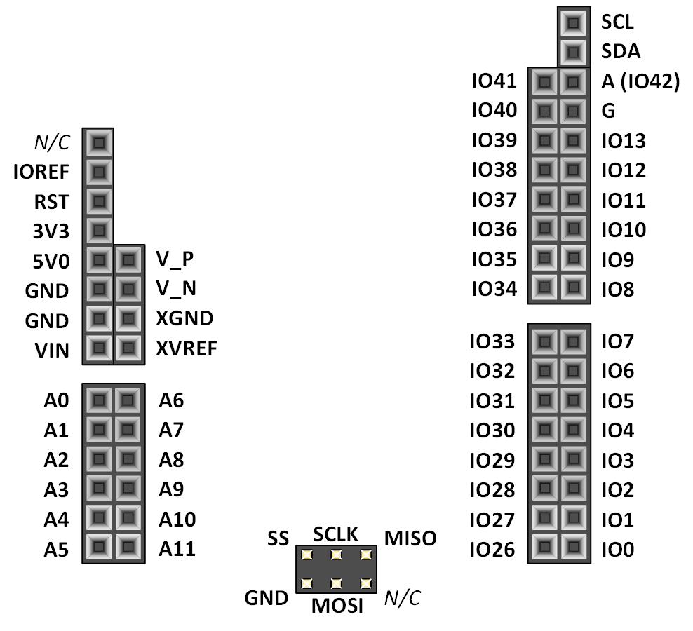
Figure 9.1. Shield connector pin diagram.
Pin Name
Shield Function
Arty S7 Connection
Shared
Connections
IO0-IO9, A
(IO42), A10-
A11
General purpose
I/O pins
See Section titled “Shield Digital I/O”
–
IO26-IO33
General purpose
I/O pins
See Section titled “Shield Digital I/O”
Pmod JD
IO34-IO41
General purpose
I/O pins
See Section titled “Shield Digital I/O”
Pmod JC
SCL
I2C Clock
See Section titled “Shield Digital I/O”
–
SDA
I2C Data
See Section titled “Shield Digital I/O”
–
IO13
General purpose
I/O, SPI Clock
See Section titled “Shield Digital I/O”
SCLK pin of SPI
Connector
IO11
General purpose
I/O, SPI Data out
See Section titled “Shield Digital I/O”
MOSI pin of SPI
Connector
IO12
General purpose
I/O, SPI Data in
See Section titled “Shield Digital I/O”
MISO pin of SPI
Connector
IO10
General purpose
I/O, SPI Slave
Select
See Section titled “Shield Digital I/O”
SS pin of SPI
Connector
A0-A5
Single-Ended
Analog Input
See Section titled “Shield Analog I/O”
–