3/15/2018 Arty S7 Reference Manual [Reference.Digilentinc] Arty S7 Reference Manual The Arty S7 board features the new Xilinx Spartan-7 FPGA and is the latest member of the Arty FPGA development board family from Digilent. The Spartan-7 FPGA offers the most size, performance, and cost-conscious design engineered with the latest technologies from Xilinx and is fully compatible with Vivado Design Suite versions 2017.3 and newer.
3/15/2018 Arty S7 Reference Manual [Reference.Digilentinc] https://reference.digilentinc.
/15/2018 Arty S7 Reference Manual [Reference.Digilentinc] https://reference.digilentinc.
3/15/2018 Arty S7 Reference Manual [Reference.Digilentinc] https://reference.digilentinc.
3/15/2018 Arty S7 Reference Manual [Reference.
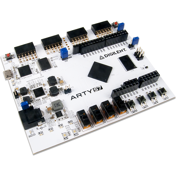
3/15/2018 Arty S7 Reference Manual [Reference.Digilentinc] 32 total FPGA I/O (16 shared with shield connector) Arduino/chipKIT Shield connector 45 total FPGA I/O (16 shared with Pmod connectors) 6 Single-ended 0-3.3V Analog inputs to XADC 3 (4*) Differential 0-1.0V Analog input pairs to XADC (*S7-25 variant value in parentheses where different) (https://reference.digilentinc.com/_detail/reference/programmable-logic/arty-s7/labelled_photo.
3/15/2018 Arty S7 Reference Manual [Reference.Digilentinc] Callout Description Callout Description 10 Arduino/ChipKIT shield connectors 20 Analog devices ADP 5052 power supply Purchasing Options The Arty S7 can be purchased with either a XC7S50 or XC7S25 FPGA loaded. These two Arty S7 product variants are referred to as the Arty S7-50 and Arty S7-25, respectively.
3/15/2018 Arty S7 Reference Manual [Reference.Digilentinc] (https://reference.digilentinc.com/_detail/reference/programmable-logic/arty-s7/arty-s7-bottom-rev.png?id=reference%3Aprogrammable-logic%3Aartys7%3Areference-manual) Software Support The Arty S7 is fully compatible with the high-performance Vivado ® Design Suite versions 2017.3 and newer. It is supported under the free WebPACK™ installation option - which does not require a license - so designs can be implemented at no additional cost.
3/15/2018 Arty S7 Reference Manual [Reference.Digilentinc] MicroBlaze programs in C and C++. After the IPI to XSDK handoff, XSDK is automatically configured to include libraries and examples for the peripheral blocks you've included in your SoC. At this point, programming the Arty S7 is very similar to programming other SoC or microcontroller platforms: Programs are written in C, programmed into board over USB, and then optionally debugged in hardware.
3/15/2018 Arty S7 Reference Manual [Reference.Digilentinc] (https://reference.digilentinc.com/_detail/reference/programmable-logic/arty-s7/arty-s7-power-rev-e.png?id=reference%3Aprogrammable-logic%3Aartys7%3Areference-manual) Figure 1.1. Arty S7 Power Circuit. The USB port can deliver enough power for the vast majority of designs. However, a few demanding applications, including any that drive multiple peripheral boards, might require more power than the USB port can provide.
3/15/2018 Arty S7 Reference Manual [Reference.Digilentinc] Maximum Current Supply Circuits Device 3.3V FPGA I/O, Clocks, Flash, PMODs, LEDs, Buttons, Switches, USB port IC11: Dialog Semiconductor DA9062 2.0A 1.0V FPGA Core and Block RAM () IC11: Dialog Semiconductor DA9062 2.5A 1.8V FPGA Auxiliary IC11: Dialog Semiconductor DA9062 1.5A 1.35V DDR3L and associated FPGA bank IC11: Dialog Semiconductor DA9062 2.5A 0.675V DDR3L IC15: Diodes Incorporated AP2303 1.75A 1.
3/15/2018 Arty S7 Reference Manual [Reference.Digilentinc] (https://reference.digilentinc.com/_detail/reference/programmable-logic/arty-s7/arty-s7-config.png?id=reference%3Aprogrammable-logic%3Aartys7%3Areference-manual) Figure 2.1. Arty S7 FPGA Configuration. Figure 2.1 shows the different options available for configuring the FPGA. An on-board “mode” jumper (JP1) selects whether the FPGA will be programmed by the Quad-SPI flash on power up.
3/15/2018 Arty S7 Reference Manual [Reference.Digilentinc] Memory type DDR3 SDRAM Max. clock period 3077ps (650Mbps data rate) Memory part MT41K128M16XX-15E Memory Voltage 1.35V Data width 16 Data mask Enabled Recommended Input Clock Period 10000ps (100.000 MHz ()) Output Driver Impedance Control RZQ/6 Controller Chip Select pin Enabled Rtt (nominal) – On-die termination RZQ/6 Internal Vref Enabled Internal termination impedance 50ohms Table 3.1. DDR3L settings for the Arty S7.
3/15/2018 Arty S7 Reference Manual [Reference.Digilentinc] (https://reference.digilentinc.com/_detail/reference/programmable-logic/arty-s7/arty-s7-flash.png?id=reference%3Aprogrammable-logic%3Aartys7%3Areference-manual) Figure 4.1. Arty S7 SPI flash. 5 Oscillators/Clocks The Arty S7 board includes a 12 MHz () crystal oscillator connected to pin F14 (an MRCC input on bank 15) and a 100 MHz () crystal oscillator connected to pin R2 (an MRCC input on bank 34).
3/15/2018 Arty S7 Reference Manual [Reference.Digilentinc] (https://reference.digilentinc.com/_detail/reference/programmable-logic/arty-s7/arty-s7-uart.png?id=reference%3Aprogrammable-logic%3Aartys7%3Areference-manual) Figure 6.1. UART Connections. 7 Basic I/O The Arty S7 board includes two tri-color LEDs, 4 switches, 4 push buttons, 4 individual LEDs, and a reset button, as shown in Figure 8.1.
3/15/2018 Arty S7 Reference Manual [Reference.Digilentinc] (https://reference.digilentinc.com/_detail/reference/programmable-logic/arty-s7/arty-s7-gpio.png?id=reference%3Aprogrammable-logic%3Aartys7%3Areference-manual) Figure 7.1. Arty S7 GPIO (). The four individual high-efficiency LEDs are anode-connected to the FPGA via 330-ohm resistors, so they will turn on when a logic high voltage is applied to their respective I/O pin.
3/15/2018 Arty S7 Reference Manual [Reference.Digilentinc] Pmod JA Pmod JB Pmod JC Pmod JD Pin 8 M17 P15 P13 R11 Pin 9 M18 N15 R13 T11 Pin 10 N18 P16 V14 U11 Table 8.1. Arty S7 Pmod Pinout. 8.1 Standard Pmod The standard Pmod connectors are connected to the FPGA via 200 Ohm series resistors. The series resistors prevent short circuits that can occur if the user accidentally drives a signal that is supposed to be used as an input.
3/15/2018 Arty S7 Reference Manual [Reference.Digilentinc] (https://reference.digilentinc.com/_media/arty/arty_shield_pins.png) Figure 9.1. Shield connector pin diagram.
3/15/2018 Arty S7 Reference Manual [Reference.
3/15/2018 Arty S7 Reference Manual [Reference.Digilentinc] Absolute Minimum Voltage Recommended Minimum Operating Voltage Recommended Maximum Operating Voltage Absolute Maximum Voltage Powered -0.4 V -0.2 V 3.4 V 3.75 V Unpowered -0.4 V N/A N/A 0.55 V Table 9.1.1. Shield Voltage Specifications For more information on the electrical characteristics of the pins connected to the FPGA, please see the Spartan-7 datasheet (https://www.xilinx.
3/15/2018 Arty S7 Reference Manual [Reference.Digilentinc] The pins labeled V_P and V_N are connected to the VP_0 and VN_0 dedicated analog inputs of the FPGA. This pair of pins can also be used as a differential analog input with voltage between 0-1V, but they cannot be used as Digital I/O. The capacitor in the circuit shown in Figure 9.2.2 for this pair of pins is loaded on the Arty S7. (https://reference.digilentinc.com/_media/reference/programmable-logic/arty/arty_shield_analog_single.png) Figure 9.
3/15/2018 Arty S7 Reference Manual [Reference.Digilentinc] (https://twitter.com/digilentinc) (https://www.facebook.com/Digilent) (https://www.youtube.com/user/DigilentInc) (https://instagram.com/digilentinc) (https://github.com/digilent) (https://www.reddit.com/r/digilent) (https://www.linkedin.com/company/1454013) (https://www.flickr.com/photos/127815101@N07) https://reference.digilentinc.


