
Data Sheet


2/17/2018 Pcam 5C Reference Manual [Reference.Digilentinc]
https://reference.digilentinc.com/reference/add-ons/pcam-5c/reference-manual 8/11
Further information on the details of MIPI CSI-2 and D-PHY are beyond the scope of this document. Digilent provides open source MIPI
CSI-2 and D-PHY Vivado IP cores that can be studied to learn more. These IP cores are included in the Digilent Vivado Library
(https://github.com/Digilent/vivado-library).
The SCCB on the Pcam 5C is a two-pin bus used to access the control registers for the OV5640 image sensor. The bus behaves the same
way as an I2C bus, and can be treated exactly the same. This means it can be controlled using existing I2C IP cores or RTL. For a more
complete description of how an I2C bus works, see the I2C Fundamentals Guide
(https://reference.digilentinc.com/learn/fundamentals/communication-protocols/i2c/start).
It is expected that the host provide 1.5 KOhm pull-up resistors on both SCL and SDA. The attached host drives the clock (SCL) and
behaves as the master on the bus. The OV5640 acts as a slave at the I2C address 0x78.
The register map accessed with the SCCB consists of 8-bit registers organized in a 16-bit address space. The details of how register read and
write transactions occur are detailed in proprietary documentation that is available from OmniVision. Most users should not need to fully
understand how the SCCB transactions occur, and can instead rely on the libraries included with the Pcam 5C demo that use the Zynq I2C
hardware to properly read and write the OV5640 registers.
The registers that are accessed using the SCCB are used to control the OV5640 image sensor. This includes things such as initializing the
sensor, setting the output format, and enabling image processing features.
The OV5640 image sensor register map is fully documented in the OV5640 datasheet, but Digilent does not have permission to redistribute
that document. To obtain complete information on the registers, please contact OmniVision and request access to the OV5640 datasheet.
The Xilinx SDK source code for the Pcam 5C demo project described in the Software Support Section contains most of the practical
information about what registers need to be written at what time in order to use the Pcam 5C. It can be referred to as well if the more
detailed information in the datasheet is not required.
The Pcam 5C is connected to a host board via a 15-pin FFC. It ships with 10 cm cable that is pre-attached to the FFC connector on the
module. If the cable is detached from the Pcam 5C for any reason, it will need to be reinstalled. This can be done as follows:
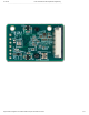
1. Locate the 15-pin FFC connector on the bottom side of the Pcam 5C.
2. Pull the black plastic tab on the edge of the connector out, away from the opening of the connector. This opens the connector.
3. Insert the FFC with the contacts facing up, toward the Pcam 5C PCB. The blue side (without contacts exposed) should be facing
down.
4. Ensure the FFC is fully inserted.
5. Gently press both sides of the black plastic tab back towards the rest of the connector to latch the FFC in.
6. Test the FFC is securely fastened by ensuring that both sides of the black plastic tab are touching the white part of the connector.
Then gently tug on the FFC to ensure it is not loose.
7. The FFC is now connected properly.
For information on how to attach the other side of the FFC to a host board, see the Pcam section of the board's reference manual.
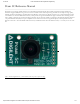
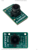
The lens solution provided on the Pcam 5C includes an M12 Lens mount and a factory-installed manual focus lens with lens cap. The lens
focus is adjusted by twisting it either clockwise or counter-clockwise.
It is possible to adjust the focus of the lens to a point that will cause most objects to be in focus, as long as they are not very close to the
lens. This can be accomplished in practice by running the Pcam 5C demo project, and then adjusting the focus of the lens until an object
several feet away looks very clear and sharp. The lens should not need to be adjusted further, unless an object close to the Pcam 5C needs to
be focused on.
For complete optical characteristics of the lens included with the Pcam 5C, please refer to its datasheet
(https://reference.digilentinc.com/_media/reference/add-ons/pcam-5c/sj2718-650_ov5640_v9.pdf). The mechanical dimensions of the M12 lens
mount are available in its datasheet (https://reference.digilentinc.com/_media/reference/add-ons/pcam-5c/pcam_5c_lens_mount.pdf) as well.
Serial Camera Control Bus (SCCB)
Register Details
FFC Attachment
Lens Adjustment