
User manual


22.8.2018 Cora Z7 Reference Manual [Reference.Digilentinc]
https://reference.digilentinc.com/reference/programmable-logic/cora-z7/reference-manual 12/20
modes, but does not support SPI mode. Based on the Zynq Technical Reference manual
(http://www.xilinx.com/support/documentation/user_guides/ug585-Zynq-7000-TRM.pdf), SDIO host mode is the only mode supported.
Signal Name Description Zynq Pin SD Slot Pin
SD_D0 Data[0] MIO42 7
SD_D1 Data[1] MIO43 8
SD_D2 Data[2] MIO44 1
SD_D3 Data[3] MIO45 2
SD_CCLK Clock MIO40 5
SD_CMD Command MIO41 3
SD_CD Card Detect MIO47 9
Table 6.1. microSD pinout
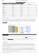
The SD slot is powered from the 3.3V rail, but is connected through MIO Bank 1/501 (1.8V). Therefore, a TI TXS02612 level shifter is
used to perform the necessary translation. The TXS02612 is actually a 2-port SDIO port expander, but only its level shifter function is
used. The connection diagram can be seen in Figure 6.1. Mapping out the correct pins and configuring the interface is handled by the
Cora Z7 Zynq presets file, available through the Cora Z7 Resource Center (https://reference.digilentinc.com/reference/programmable-
logic/cora-z7/start).
(https://reference.digilentinc.com/_detail/reference/programmable-logic/cora-z7/cora-micro-sd.png?id=reference%3Aprogrammable-logic%3Acora-
z7%3Areference-manual)
Figure 6.1. microSD slot signals
Both low speed and high speed cards are supported, as the maximum clock frequency is 50 MHz (). A Class 4 card or better is
recommended.
Refer to section 3.1, microSD Boot Mode, for information on how to boot the Cora Z7 from an SD card. For more information, consult
the Zynq Technical Reference manual (http://www.xilinx.com/support/documentation/user_guides/ug585-Zynq-7000-TRM.pdf).
The Cora Z7 implements one of the two available PS USB OTG interfaces on the Zynq device. A Microchip USB3320 USB 2.0
Transceiver Chip with an 8-bit ULPI interface is used as the PHY. The PHY features a complete HS-USB Physical Front-End
supporting speeds of up to 480Mbs. The PHY is connected to MIO Bank 1/501, which is powered at 1.8V. The USB0 peripheral is used
on the PS, connected through MIO[28-39]. The USB OTG interface is configured to act as an embedded host. USB OTG and USB
device modes are not supported.
The Cora Z7 is technically an “embedded host”, because it does not provide the required 150 µF of capacitance on VBUS required to
qualify as a general purpose host. It is possible to modify the Cora Z7 so that it complies with the general purpose USB host
requirements by loading C35 with a 150 µF capacitor. Only those experienced at soldering small components on PCBs should attempt
this rework. Many USB peripheral devices will work just fine without loading C35. Whether the Cora Z7 is configured as an embedded
host or a general purpose host, it can provide 1A on the 5V VBUS line.
Note that if your design uses the USB Host port (embedded or general purpose), then the Cora Z7 should be powered via a wall adapter
capable of providing more power.
7 USB Host