
User manual


22.8.2018 Cora Z7 Reference Manual [Reference.Digilentinc]
https://reference.digilentinc.com/reference/programmable-logic/cora-z7/reference-manual 14/20
For more information on using the Gigabit Ethernet MAC, refer to the Zynq Technical Reference manual
(http://www.xilinx.com/support/documentation/user_guides/ug585-Zynq-7000-TRM.pdf).
The Cora Z7 provides a 50 MHz () clock to the Zynq PS_CLK input, which is used to generate the clocks for each of the Processing
System (PS) subsystems. The 50 MHz () input allows the processor to operate at a maximum frequency of 650 MHz () and the DDR3
memory controller to operate at a maximum of 525 MHz () (1050 Mbps). The Cora Z7 Zynq Preset file available within the Digilent
Vivado Board File package (Installation Instructions (https://reference.digilentinc.com/vivado/installing-
vivado/start#installing_digilent_board_files)) can be imported into the Zynq Processing System IP core in a Vivado project to properly
configure the Zynq to work with the 50 MHz () input clock.
The PS has a dedicated Phase-Locked Loop (PLL) capable of generating up to four reference clocks, each with settable frequencies, that
can be used to clock custom logic implemented in the Programmable Logic (PL). Additionally, the Cora Z7 provides an external 125
MHz () reference clock directly to pin H16 of the PL. The external reference clock allows the PL to be used completely independently of
the PS, which can be useful for simple applications that do not require the processor.
The PL of the Zynq also includes Mixed-Mode Clock Managers (MMCM) and PLLs that can be used to generate clocks with precise
frequencies and phase relationships. Any of the four PS reference clocks or the 125 MHz () external reference clock can be used as an
input to the MMCMs and PLLs. Both the Cora Z7-07S and Z7-10 include 2 MMCM's and 2 PLL's. For a full description of the
capabilities of the Zynq PL clocking resources, refer to the “7 Series FPGAs Clocking Resources User Guide” available from Xilinx.
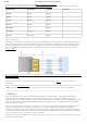
Figure 9.1 outlines the clocking scheme used on the Cora Z7. Note that the reference clock output from the Ethernet PHY is used as the
125 MHz () reference clock to the PL, in order to cut the cost of including a dedicated oscillator for this purpose. Keep in mind that
CLK125 will be disabled when the Ethernet PHY (IC1) is held in hardware reset by driving the PHYRSTB signal low.
Figure 9.1. Cora Z7 Clocking
The Zynq Processing System (PS) supports external power-on reset signals. The power-on reset is the master reset of the entire chip.
This signal resets every register in the device capable of being reset. The Cora Z7 drives this signal from the nRESET signal of the
DA9062 DC-DC converter system in order to hold the system in reset until all power supplies are valid. A push-button, labeled RESET,
can be used to toggle the power-on reset signal.
Note: The power-on reset will not reset attached shields.
The external system reset, labeled SRST, resets the Zynq device without disturbing the debug environment. For example, the previous
break points set by the user remain valid after system reset. Due to security concerns, system reset erases all memory content within the
PS, including the OCM. The PL is also cleared during a system reset. System reset does not cause the boot mode strapping pins to be re-
sampled.
The SRST button also causes the CK_RST signal to toggle and trigger a reset on any attached shields.
9 Clock Sources
10 Reset Sources
10.1 Power-on Reset
10.2 Processor Subsystem Reset