
User manual


22.8.2018 Cora Z7 Reference Manual [Reference.Digilentinc]
https://reference.digilentinc.com/reference/programmable-logic/cora-z7/reference-manual 17/20
Pin Name Shield Function Cora Z7 Connection
SCK SPI Clock See Section titled “Shield Digital I/O”
SS SPI Slave Select See Section titled “Shield Digital I/O”
MOSI () SPI Master-Out
Slave-In
See Section titled “Shield Digital I/O”
MISO () SPI Master-In
Slave-In
See Section titled “Shield Digital I/O”
A0-A5 Single-Ended
Analog Input
See Section titled “Shield Analog I/O”
A6-A11 Differential
Analog Input
See Section titled “Shield Analog I/O”
V_P, V_N Dedicated
Differential
Analog Input
See Section titled “Shield Analog I/O”
XGND XADC Analog
Ground
Connected to net used to drive the XADC ground reference on the FPGA (VREFN)
Not Connected Not Connected
IOREF Digital I/O
Voltage reference
Connected to the Cora Z7 3.3V Power Rail (See the “Power Supplies” section)
RST Reset to Shield Connected to the red “SRST” button and a Digital I/O of the FPGA. When JP1 is
shorted, it is also connected to the DTR signal of the FTDI USB-UART bridge.
3V3 3.3V Power Rail Connected to the Cora Z7 3.3V Power Rail (See the “Power Supplies” section)
5V0 5.0V Power Rail Connected to the Cora Z7 5.0V Power Rail (See the “Power Supplies” section)
GND (), G Ground Connected to the Ground plane of Cora Z7
Table 13.1. Cora Z7 Shield Pinout
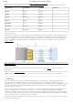
The pins connected directly to the FPGA can be used as general purpose inputs or outputs. These pins include the I2C, SPI, and general
purpose I/O pins. There are 200 Ohm series resistors between the FPGA and the digital I/O pins to help provide protection against
accidental short circuits. The absolute maximum and recommended operating voltages for these pins are outlined in Table 13.1.1.
Absolute
Minimum Voltage
Recommended Minimum
Operating Voltage
Recommended Maximum
Operating Voltage
Absolute
Maximum Voltage
Powered -0.4 V -0.2 V 3.4 V 3.75 V
Unpowered -0.4 V N/A N/A 0.55 V
Table 13.1.1. Shield Voltage Specifications
For more information on the electrical characteristics of the pins connected to the FPGA, please see the Zynq-7000 datasheet
(https://www.xilinx.com/support/documentation/data_sheets/ds190-Zynq-7000-Overview.pdf) from Xilinx.
The pins on the shield connector typically used for I2C signals are labeled as SCL and SDA. On the Cora Z7, these signals are each
attached to a pull-up resistor. While these pins can still be used as digital I/O, these pull-ups should be kept in mind.
13.1 Shield Digital I/O
13.2 Shield Analog I/O