
User manual


22.8.2018 Cora Z7 Reference Manual [Reference.Digilentinc]
https://reference.digilentinc.com/reference/programmable-logic/cora-z7/reference-manual 4/20
Gigabit Ethernet PHY with 48-bit globally unique EUI-48/64™ compatible identifier available on sticker
USB-JTAG programming circuitry
USB-UART bridge
USB OTG PHY (supports host only)
Push-buttons and LEDs
Two Push-buttons
Two RGB LEDs
Expansion Connectors
Two Pmod connectors
16 Total FPGA I/O
Arduino/chipKIT Shield connector
Up to 49 Total FPGA Digital I/O
6 Single-ended 0-3.3V Analog inputs to XADC
8 Differential 0-1.0V Analog inputs to XADC
Unloaded expansion header
12 additional FPGA Digital I/O
(*Z7-07S variant in parentheses where different)
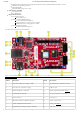
(https://reference.digilentinc.com/_detail/reference/programmable-logic/cora-z7/cora-z7-callout.png?id=reference%3Aprogrammable-logic%3Acora-
z7%3Areference-manual)
Callout Description Callout Description
1 Power select jumper (Ext. supply / USB) 11 microSD card slot (underside of board)
2 Power jack (for optional ext. supply) 12 USB host port
3 Shared USB JTAG / UART port 13 FPGA programming DONE LED ()
4 Unloaded expansion header 14 Processor subsystem reset button
5 Pmod connectors 15 Ethernet port
6 SPI header (Arduino/ChipKIT compatible) 16 Power on reset button
7 Arduino/ChipKIT shield connectors 17 Power good LED ()
8 Programming mode jumper (JTAG / microSD) 18 Zynq-7000