
User manual


22.8.2018 Cora Z7 Reference Manual [Reference.Digilentinc]
https://reference.digilentinc.com/reference/programmable-logic/cora-z7/reference-manual 6/20
The Cora Z7 requires a 5 Volt power source to operate. This power source can come from the Digilent USB-JTAG port (J12) or it can
be derived from a 5 Volt DC power supply connected to the Power Jack (J15). Unlike other Digilent FPGAs, the Cora Z7 cannot be
powered through the Shield Header.
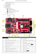
A red power-good LED () (LD7), driven by the 3.3V output (VCC3V3) of the DA9062 regulator, indicates that the board is receiving
power and that the onboard supplies are functioning as expected. If this LED () does not illuminate when an acceptable power supply is
connected, please contact your distributor or Digilent Support (http://forum.digilentinc.com) for further help.
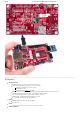
Figure 1.1 Cora Z7 Power Circuit
The USB port can deliver enough power for the vast majority of designs. However, a few demanding applications, including any that
drive multiple peripheral boards, might require more power than the USB port can provide. Also, some applications may need to run
without being connected to a PC’s USB port. In these instances an external power supply can be used by plugging into the Power Jack
(J15). The supply must use a coaxial, center-positive 2.1mm (or 2.5mm) internal-diameter plug, and provide a DC voltage of 5 Volts. The
supply should provide a minimum current of 1 amp. Ideally, the supply should be capable of providing 20 Watts of power (5 Volts DC, 4
amps). If the USB port is to be used to deliver power, the Power Select Jumper (JP3) should be set to “USB”. If an external power supply
is to be used, JP3 should be set to “EXT” instead.
Voltage regulator circuits from Dialog Semiconductor and ON Semiconductor create the required 3.3V, 1.8V, 1.35V, and 1.00V supplies
from the 5V power source. In the event that an external supply or battery pack is used, the on-board Monolithic Power Systems 5V
regulator (IC12) provides the 5V source. Table 1.1 provides additional information (typical currents depend strongly on FPGA
configuration and the values provided are typical of medium size/speed designs). The 0.675V supply is created by a simple Voltage
divider circuit consisting of two 10 KOhm resistors, sourced from the 1.35V rail.
Supply Circuits Device
Maximum
Current
5.0V Onboard Regulators, Arduino/chipKit Shield Connector, RGB
LEDs
IC4: ON Semiconductor
NCP380
3.3V FPGA I/O, USB port, Ethernet IC15: Dialog Semiconductor
DA9062
2A
1.0V FPGA, Ethernet IC15: Dialog Semiconductor
DA9062
2.5A
1.8V FPGA Auxiliary, USB port, Ethernet IC15: Dialog Semiconductor
DA9062
1.5A
1.35V FPGA, DDR3L memory IC15: Dialog Semiconductor
DA9062
2.5A
1.8V FPGA XADC IC15: Dialog Semiconductor
DA9062
100mA
Functional Description
1 Power Supplies
1)