
User manual


22.8.2018 Analog Discovery Impedance Analyzer Reference Manual [Reference.Digilentinc]
https://reference.digilentinc.com/reference/add-ons/impedance-analyzer/reference-manual 4/7
Equipped with automatically selectable reference resistances
Compatible with the Analog Discovery Legacy, Analog Discovery 2, and Analog Discovery NI-Edition
Allows auto-scaling
The Analog Discovery Impedance Analyzer is compatible with the following:
Analog Discovery Legacy
Analog Discovery 2
Analog Discovery 2-NI Edition
This reference manual applies to Revision A of the Analog Discovery Impedance Analyzer.
J1 - 2×15 Analog Discovery connector - Interfaces the Impedance Analyzer with the Analog Discovery
J2 - 1×2 Terminal Bloc - Used for connecting in circuit the unknown impedance
The Analog Discovery's digital I/O pins are used to control the relays in order to select the needed value for the reference impedance.
Each relay driver uses two I/Os to control one relay.
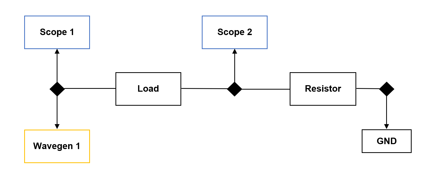
The Analog Discovery Impedance Analyzer is used to analyze capacitive and inductive elements. It uses the WaveGen 1, Oscilloscope device
instruments, and a reference resistor.
The impedance analyzer circuit is constructed as in the circuit below. Load represents the inductive or capacitive item to be analyzed and
Resistor is the reference resistor that is already loaded on the board. The resistor value depends on the load value and frequency.
(https://reference.digilentinc.com/_media/reference/add-ons/impedance-analyzer/circuit1.png)
The approximate resistor needed for different loads are the following:
Capacitance Ref Resistor Inductance
Overview
Features
Compatible Products
About this Document
Functional Description
Connectors and Jumpers
Digital Pins used for configuration
Measuring the impedance