
User Manual


0.1% resistors and 1% capacitors in all the critical analog signal paths
Capacitive trimmers for balancing the Scope Input Divider and Gain Selection
No other mechanical trimmers (as these are big, expensive, unreliable and affected by vibrations, aging, and temperature drifts)
Software calibration, at manufacturing
User software calibration, as an option
A software calibration is performed on each device as a part of the manufacturing test. Reference signals are connected to the Scope inputs. A set of
measurements is used to identify all the DC errors (Gain, Offset) of each analog stage. Correction (Calibration) parameters are computed and stored in the
Calibration Memory, on the Zmod
ADC () device, both as Factory Calibration Data and User Calibration Data. The WaveForms software allows the user
performing an in-house calibration and overwrite the User Calibration Data. Returning to Factory Calibration is always possible.
The Software reads the calibration parameters from the Zmod
ADC () MCU via the I2C bus and uses them to correct the acquired signals. The structure of
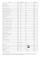
the calibration data is shown below:
Table 3. The Calibration Data Structure []
Heading 1
Name
Size (Bytes) Type
Flash Address
(Factory Calibration)
EEPROM () Address
(User Calibration)
Magic ID 1 uchar 0xAD 0x8100 0x7000
Calibration Time 4 unix timestamp 0x8104 0x7004
Channel 1 LG Gain CG 4 float32 0x8108 0x7008
Channel 1 LG Offset CA 4 float32 0x810C 0x700C
Channel 1 HG Gain CG 4 float32 0x8110 0x7010
Channel 1 HG Offset CA 4 float32 0x8114 0x7014
Channel 2 LG Gain CG 4 float32 0x8118 0x7018
Channel 2 LG Offset CA 4 float32 0x811C 0x701C
Channel 2 HG Gain CG 4 float32 0x8120 0x7020
Channel 2 HG Offset CA 4 float32 0x8124 0x7024
Reserved Area 68 - 0x8168 0x7068
Log 22 string 0x817E 0x707E
CRC 1 uchar 0x817F 0x707F
Table 4. The EEPROM Memory Map []
Address Function Size (Bytes)
0x7000 - 0x707F User Calibration 128
0x7080 - 0x70FF Future Use 128
At the power up the
EEPROM () memory is protected against write operations. To disable the write protection one has to write a magic number to a magic
address over I2C. To re-enable the write protection one has to write a any other number to the magic address.
Table 5. The Write Protection Disable magic number and address []
Magic Number Magic Adress
0xD2 0x6FFF
This block includes the internal power supplies.
The Zmod
ADC () gets the digital rails from the carrier board, via the SYZYGY connector:
VCC5V0 - used for relays and analog supplies
VCC3V3 - used for the MCU and analog supplies
Vadj = 1.8V - used for the
ADC () digital rail
4. Power Supplies and Control