
User Manual

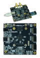


An overview of the power circuit is shown in Figure 1.1:
Figure 1.1: Power Circuit Overview
All on-board power supplies are automatically sequenced on when a power supply, whether USB or an external supply connected to the
barrel jack (), is connected to the board.
The power indicator
LED (), labeled “LDP”, is illuminated (color) when all supply rails reach their nominal voltage.
An additional indicator
LED (), labeled “ENVADJ”, is illuminated when the VIO supply associated with the SYZYGY port (VADJ) is
powered.
The USB104 A7 can be powered either over USB or via a wall wart supply with a barrel jack, via connector J6. The wall wart supply must
use a center-positive 2.1 mm internal-diameter plug and deliver between 4.65V and 5.5V DC. It should also be able to provide at least 5 A
(25 Watts) in order to support power-hungry FPGA design and external peripherals. A compatible 30 Watt power supply ships with the
USB104 A7.
The power input source is automatically determined by the supply circuitry. The barrel jack supply is preferred. If a supply is connected
when the board is already powered through USB, then the board will seamlessly switch over to the external supply without brownout or
reset. If the external supply is disconnected, the board will switch back to USB power, but the onboard supplies will temporarily shut
down and then sequence back on.
Table 1.1.1: USB104 A7 Power Input Specifications
Connector Type Connector Label Schematic Net Name Min/Rec/Max Voltage Max Current Consumption
Barrel Jack J6 VEXT5V0 4.65/5/5.5 6.0A/30W
USB Type B J2 VBUS 4.65/5/5.5 2.0A/10W
Table 1.2.1 describes the characteristics of the USB104 A7's on-board power rails. It can be used to estimate power consumption for a
project, or determine how much current attached peripherals can draw before being limited.
Table 1.2.1: USB104 A7 Power Rail Specifications
1.1. Power Input Source
1.2. Power Specifications