
Data Sheet


PYNQ-Z1 Board Reference Manual
Copyright Digilent, Inc. All rights reserved.
Other product and company names mentioned may be trademarks of their respective owners.
Page 3 of 25
A USB 2.0 port can deliver maximum 0.5A of current according to the specifications. This should provide enough
power for lower complexity designs. More demanding applications, including any that drive multiple peripheral
boards or other USB devices, might require more power than the USB port can provide. In this case, power
consumption will increase until it’s limited by the USB host. This limit varies a lot between manufacturers of host
computers and depends on many factors. When in current limit, once the voltage rails dip below their nominal
value, the Zynq is reset by the Power-on Reset signal and power consumption returns to its idle value. Also, some
applications may need to run without being connected to a PC’s USB port. In these instances an external power
supply or battery can be used.
An external power supply (e.g. wall wart) can be used by plugging it into the power jack (J18) and setting jumper
JP5 to “REG”. The supply must use a coax, center-positive 2.1mm internal-diameter plug, and deliver 7VDC to
15VDC. Suitable supplies can be purchased from the Digilent website or through catalog vendors like DigiKey.
Power supply voltages above 15VDC might cause permanent damage. A suitable external power supply is included
with the PYNQ-Z1 accessory kit.
Similar to using an external power supply, a battery can be used to power the PYNQ-Z1 by attaching it to the shield
connector and setting jumper JP5 to “REG”. The positive terminal of the battery must be connected to the pin
labeled “VIN” on J7, and the negative terminal must be connected to the pin labeled GND on J7.
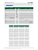
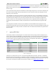
The on-board Texas Instruments TPS65400 PMU creates the required 3.3V, 1.8V, 1.5V, and 1.0V supplies from the
main power input. Table 1.1 provides additional information (typical currents depend strongly on Zynq
configuration and the values provided are typical of medium size/speed designs).
All on-board power supplies are enabled or disabled by the power switch SW4. The power indicator LED (LD13) is
on when all the supply rails reach their nominal voltage.
Supply
Circuits
Current (max/typical)
3.3V
FPGA I/O, USB ports, Clocks, Ethernet, SD slot, Flash, HDMI
1.6A/0.1A to 1.5A
1.0V
FPGA, Ethernet Core
2.6A/0.2A to 2.1A
1.5V
DDR3
1.8A/0.1A to 1.2A
1.8V
FPGA Auxiliary, Ethernet I/O, USB Controller
1.8A/0.1A to 0.6A
Table 1.1. PYNQ-Z1 power supplies.
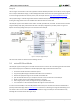
2 Zynq APSoC Architecture
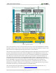
The Zynq APSoC is divided into two distinct subsystems: The Processing System (PS) and the Programmable Logic
(PL). Figure 2.1 shows an overview of the Zynq APSoC architecture, with the PS colored light green and the PL in
yellow. Note that the PCIe Gen2 controller and Multi-gigabit transceivers are not available on the Zynq-7020
device.