
Data Sheet


PYNQ-Z1 Board Reference Manual
Copyright Digilent, Inc. All rights reserved.
Other product and company names mentioned may be trademarks of their respective owners.
Page 5 of 25
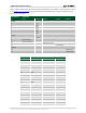
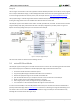
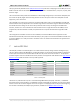
Table 2.1 depicts the external components connected to the MIO pins of the PYNQ-Z1. The Zynq Presets File found
on the PYNQ-Z1 Resource Center can be imported into EDK and Vivado Designs to properly configure the PS to
work with these peripherals.
MIO 500 3.3 V
Peripherals
Pin
ENET 0
SPI Flash
USB 0
Shield
UART 0
0 (N/C)
1
CS
2
DQ0
3
DQ1
4
DQ2
5
DQ3
6
SCLK
7 (N/C)
8
SLCK FB
9
Ethernet Reset
10
Ethernet Interrupt
11
USB Over Current
12
Shield Reset
13 (N/C)
14
UART Input
15
UART Output
MIO 501 1.8V
Peripherals
Pin
ENET 0
USB 0
SDIO 0
16
TXCK
17
TXD0
18
TXD1
19
TXD2
20
TXD3
21
TXCTL
22
RXCK
23
RXD0
24
RXD1
25
RXD2
26
RXD3
27
RXCTL
28
DATA4
29
DIR
30
STP
31
NXT
32
DATA0
33
DATA1
34
DATA2
35
DATA3
36
CLK
37
DATA5
38
DATA6