
Data Sheet


PYNQ-Z1 Board Reference Manual
Copyright Digilent, Inc. All rights reserved.
Other product and company names mentioned may be trademarks of their respective owners.
Page 8 of 25
3.2 Quad SPI Boot Mode
The PYNQ-Z1 has an onboard 16MB Quad-SPI Flash that the Zynq can boot from. Documentation available from
Xilinx describes how to use Xilinx SDK to program a Zynq Boot Image into a Flash device attached to the Zynq. Once
the Quad SPI Flash has been loaded with a Zynq Boot Image, the following steps can be followed to boot from it:
1. Attach a power source to the PYNQ-Z1 and select it using JP5.
2. Place a single jumper on JP4, shorting the two center pins (labeled “QSPI”).
3. Turn the board on. The board will now boot the image stored in the Quad SPI flash.
3.3 JTAG Boot Mode
When placed in JTAG boot mode, the processor will wait until software is loaded by a host computer using the
Xilinx tools. After software has been loaded, it is possible to either let the software begin executing, or step
through it line by line using Xilinx SDK.
It is also possible to directly configure the PL over JTAG, independent of the processor. This can be done using the
Vivado Hardware Server.
The PYNQ-Z1 is configured to boot in Cascaded JTAG mode, which allows the PS to be accessed via the same JTAG
port as the PL. It is also possible to boot the PYNQ-Z1 in Independent JTAG mode by loading a jumper in JP2 and
shorting it. This will cause the PS to not be accessible from the onboard JTAG circuitry, and only the PL will be
visible in the scan chain. To access the PS over JTAG while in independent JTAG mode, users will have to route the
signals for the PJTAG peripheral over EMIO, and use an external device to communicate with it.
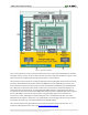
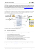
4 Quad SPI Flash
The PYNQ-Z1 features a Quad SPI serial NOR flash. The Spansion S25FL128S is used on this board. The Multi-I/O SPI
Flash memory is used to provide non-volatile code and data storage. It can be used to initialize the PS subsystem as
well as configure the PL subsystem.
The relevant device attributes are:
16 MB
x1, x2, and x4 support
Bus speeds up to 104 MHz, supporting Zynq configuration rates @ 100 MHz. In Quad SPI mode, this
translates to 400Mbs
Powered from 3.3V
The SPI Flash connects to the Zynq-7000 APSoC and supports the Quad SPI interface. This requires connection to
specific pins in MIO Bank 0/500, specifically MIO[1:6,8] as outlined in the Zynq datasheet. Quad-SPI feedback mode
is used, thus qspi_sclk_fb_out/MIO[8] is left to freely toggle and is connected only to a 20K pull-up resistor to 3.3V.
This allows a Quad SPI clock frequency greater than FQSPICLK2 (See the Zynq Technical Reference manual for more
on this).