
MCC USB-1808X: High-Speed, High-Precision, Simultaneous USB DAQ Device - User Guide
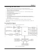

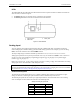
Table Of Contents
- About this User's Guide
- Introducing the USB-1808X
- Installing the USB-1808X
- Functional Details
- Specifications
- EU Declaration of Conformity

USB-1808X User's Guide Functional Details
10
LEDs
The USB-1808X has two LED indicators that indicate the status of power and data. The LEDs are stacked one
above the other, as shown in Figure 4.
The
Status LED turns on when the device is detected by the computer.
The
Activity LED blinks when data is transferred and is off otherwise.
1
USB connector
3
Activity LED
2
Status LED
Figure 4. LED indicators
Analog input
You can configure each analog input channel for either SE or DIFF mode. MCC recommends connecting
unused analog input terminals to analog ground terminals during operation. For example, if you are not using
CH7L, connect this terminal to an available AGND terminal.
The input voltage range is software-selectable per channel for ±10 V, ±5 V, 0 V to 10 V, or 0 V to 5 V.
Analog input operations can be paced by the internal clock or by an external clock (
ICLKI – refer to Clock I/O
on page 15). They can be initiated by a digital trigger (Digital triggering on page 15) or a pattern trigger
(Pattern triggering on page 15).
Refer to Synchronous I/O – mixing analog, digital, and counter scanning on page 15 for information on running
analog input scans at the same time as other subsystem scans.
For more information about analog signal connections
For more information about analog input connections, refer to the Guide to DAQ Signal Connections (available
for download at www.mccdaq.com/support/DAQ-Signal-Connections.aspx).
Channel-Gain queue
The channel-gain queue feature allows you to configure a different gain setting for each channel. The gain
settings are stored in a channel-gain queue list that is written to local memory on the device.
The channel-gain queue list can contain up to eight unique elements. The channel list must be in increasing
order. An example of a five-element list is shown in the following table.
Sample channel-gain queue list
Element Channel Range
0
CH0H/CH0L (DIFF)
±10 V
1
CH2H/AGND (SE)
±5 V
2
CH3H/AGND (SE)
0 V to 5 V
3
CH6H/CH6L (DIFF)
0 V to 10 V
4
CH7H/CH7L (DIFF)
±5 V