
MCC USB-1808X: High-Speed, High-Precision, Simultaneous USB DAQ Device - User Guide
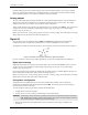
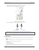
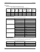
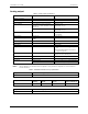
Table Of Contents
- About this User's Guide
- Introducing the USB-1808X
- Installing the USB-1808X
- Functional Details
- Specifications
- EU Declaration of Conformity

USB-1808X User's Guide Functional Details
11
Carefully match the gain to the expected voltage range on the associated channel or an over range condition
may occur. Although this condition does not damage the device, it does produce a useless full-scale reading,
and can introduce a long recovery time due to saturation of the input channel.
Analog output
The two 16-bit analog outputs (AOUT0 and AOUT1) can be updated simultaneously at a rate of 500 kS/s per
channel. Each output can be updated at a rate of 500 kS/s. The output range is fixed at ±10 V. The outputs
default to 0 V at power up, or when a reset command is issued to the device.
Analog output operations can be paced by the internal clock or by an external clock (
OCLKI – refer to Clock I/O
on page 15). They can be initiated by a digital trigger (Digital triggering on page 15) or a pattern trigger
(Pattern triggering on page 15).
Refer to Synchronous I/O – mixing analog, digital, and counter scanning on page 15 for information on running
analog output scans at the same time as other subsystem scans.
Digital I/O
You can connect up to four digital I/O lines to DIO0 through DIO3. Each digital channel is individually
configurable for input or output. During initial power on or reset, the digital pins are set for input.
The digital I/O terminals can detect the state of any TTL-level input. Refer to the schematic shown in Figure 5.
Figure 5. Schematic showing switch detection by digital channel DIO0
If you set the switch to the +5 V input, DIO0 reads TRUE (1). When set to GND, DIO0 reads FALSE (0).
Digital input scanning
Digital input operations can be paced by the internal clock or by an external clock (ICLKI – refer to Clock I/O
on page 15). They can be initiated by a digital trigger (Digital triggering on page 15) or a pattern trigger
(Pattern triggering on page 15).
If no analog inputs are being scanned, the digital inputs can sustain rates up to 200 kHz. Digital input ports can
also be read asynchronously before, during, or after an analog input scan.
Refer to Synchronous I/O – mixing analog, digital, and counter scanning on page 15 for information on running
digital input scans at the same time as other subsystem scans.
Pull-up/down configuration
All digital I/O lines are pulled down to 0 V (LO) with a 47 kΩ resistor (default). You can change the
pull-up/down configuration using the internal jumper labeled
DIO. You must remove the device housing to
access the jumper on the circuit board.
To set the jumper for pull-up or pull-down, complete the following steps.
1. Unplug the device from the computer.
2. Turn the device over and rest the top of the housing on a flat, stable surface.
Caution! The discharge of static electricity can damage some electronic components. Before removing the
USB-1808X from its housing, ground yourself using a wrist strap or touch the computer chassis or
other grounded object to eliminate any stored static charge.
3. Remove the rubber fee from the bottom of the device, and the four screws using a #1 Philips head
screwdriver.