
MCC USB-1808X: High-Speed, High-Precision, Simultaneous USB DAQ Device - User Guide
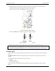
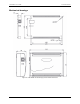
Table Of Contents
- About this User's Guide
- Introducing the USB-1808X
- Installing the USB-1808X
- Functional Details
- Specifications
- EU Declaration of Conformity

USB-1808X User's Guide Functional Details
12
4. Hold both the top and bottom sections together, turn the device over and rest it on the surface, then
carefully remove the top section of the case to expose the circuit board.
Figure 6 shows the location of the
DIO jumper on the circuit board.
Figure 6. Pull-up/down jumper location
5. Configure the DIO jumper for pull-up or pull-down, as shown in Figure 7.
Figure 7. Pull-up/down jumper configuration
6. Replace the top section of the housing and fasten it to the bottom section with the four screws.
For more information about digital signal connections
For general information about digital signal connections and digital I/O techniques, refer to the Guide to DAQ
Signal Connections (available for download at www.mccdaq.com/support/DAQ-Signal-Connections.aspx).
Counter input
Counter inputs can be read asynchronously under program control, or synchronously as part of a digital scan
group.
The
CTR0 and CTR1 terminals are 32-bit general-purpose counters that can accept frequency inputs up to
50 MHz.
The USB-1808X supports the following counter input modes:
Totalize
Period measurement
Pulse-width measurement
Counter input modes are programmable with software. Each mode supports additional counter operation
options.