
Data Sheet

3/8/2018 Arty Z7 Reference Manual [Reference.Digilentinc]
https://reference.digilentinc.com/reference/programmable-logic/arty-z7/reference-manual 18/24
(https://reference.digilentinc.com/_detail/reference/programmable-logic/arty-z7/arty-z7-audio-pdm.png?id=reference%3Aprogrammable-logic%3Aarty-
z7%3Areference-manual)
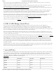
Figure 13.1.1. PWM Waveform.
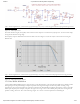
The PWM signal must be integrated to define an analog voltage. The low-pass filter 3dB frequency should be an order of magnitude lower
than the PWM frequency, so that signal energy at the PWM frequency is filtered from the signal. For example, if an audio signal must
contain up to 5 KHz of frequency information, then the PWM frequency should be at least 50 KHz (and preferably even higher). In general,
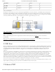
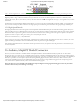
in terms of analog signal fidelity, the higher the PWM frequency, the better. Figure 13.1.2 shows a representation of a PWM integrator
producing an output voltage by integrating the pulse train. Note the steady-state filter output signal amplitude ratio to Vdd is the same as the
pulse-width duty cycle (duty cycle is defined as pulse-high time divided by pulse-window time).
(https://reference.digilentinc.com/_detail/reference/programmable-logic/arty-z7/arty-z7-audio-pwm.png?id=reference%3Aprogrammable-logic%3Aarty-
z7%3Areference-manual)
Figure 13.1.2. PWM Output Voltage.
The Zynq PS supports external power-on reset signals. The power-on reset is the master reset of the entire chip. This signal resets every
register in the device capable of being reset. The Arty Z7 drives this signal from the PGOOD signal of the TPS65400 power regulator in
order to hold the system in reset until all power supplies are valid.
A PROG push switch, labeled PROG, toggles Zynq PROG_B. This resets the PL and causes DONE to be de-asserted. The PL will remain
unconfigured until it is reprogrammed by the processor or via JTAG.
The external system reset, labeled SRST, resets the Zynq device without disturbing the debug environment. For example, the previous break
points set by the user remain valid after system reset. Due to security concerns, system reset erases all memory content within the PS,
including the OCM. The PL is also cleared during a system reset. System reset does not cause the boot mode strapping pins to be re-
sampled.
The SRST button also causes the CK_RST signal to toggle in order to trigger a reset on any attached shields.
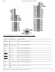
Pmod ports are 2×6, right-angle, 100-mil spaced female connectors that mate with standard 2×6 pin headers. Each 12-pin Pmod port
provides two 3.3V VCC () signals (pins 6 and 12), two Ground signals (pins 5 and 11), and eight logic signals, as shown in Figure 15.1. The
VCC () and Ground pins can deliver up to 1A of current, but care must be taken not to exceed any of the power budgets of the onboard
regulators or the external power supply (see the 3.3V rail current limits listed in the “Power Supplies” section).
14 Reset Sources
14.1 Power-on Reset
14.2 Program Push Button Switch
14.3 Processor Subsystem Reset
15 Pmod Ports