
Data Sheet

1300 Henley Court
Pullman, WA 99163
509.334.6306
www.digilentinc.com
PmodSTEP™ Reference Manual
Revised May 24, 2016
This manual applies to the PmodSTEP rev. A
DOC#: 502-276
Copyright Digilent, Inc. All rights reserved.
Other product and company names mentioned may be trademarks of their respective owners.
Page 1 of 2
Overview
The PmodSTEP provides a four channel drive for a stepper motor via the ST L293DD. Users may wire two pairs of
channels in series to drive up to 600 mA of current per channel and can view the current status of a GPIO signal
through a set of user LEDs.
1 Functional Description
The PmodSTEP utilizes ST's four channel driver, a L293DD, to drive stepper motors at higher currents than a system
board can typically provide from their logic outputs. External test point headers and LEDs are provided for easy
testing and observation of the propagation of signals.
2 Interfacing with the Pmod
The PmodSTEP communicates with the host board via the GPIO protocol.
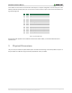
This Pmod offers headers for both 4-pin and 6-pin stepper motors. Stepper motors work by alternately energizing
the coils to different polarities inducing the stepper motor to rotate.
4-pin stepper motors only work in the bipolar configuration, requiring that the two inputs on each electromagnetic
coil are brought to the correct logic level voltages to induce current flow in the correct direction. The 6-pin stepper
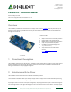
The PmodSTEP.
Stepper motor driver for 4 and 6-pin motors
Can drive both motors simultaneously
Multiple LEDs to indicate signal propagation
Jumper for optional external power
Small PCB size for flexible designs 2.8“ ×
1.3” (7.1 cm × 3.3 cm)
2×6-pin Pmod connector with GPIO
interface
Follows Digilent Pmod Interface
Specification Type 1
Features include: