Digimax 210 Programmable Thermostat User Guide
Schema of the thermostat The RF DigiMax 210 thermostat does not need any extra wiring and works within 30 meters range around the receiver RF-Max. The DigiMax 210 is equiped of a secured RF code which the RF Max will learn during the installation process. This code will assure that the receiver will only answer to messages sent by your DigiMax 210. This process is described at the end of this manual. I. To start : Remove the battery insulation strip and check unit is functioning. II.
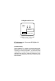
To change the “Set Point” (i.e. temperature requested), press and hold the “SET” key and at the same time press “+” or “-” to select the temperature setting. The display will show the “Set Point” until the “SET” button is released. The display will then show the ambient temperature. When the DigiMax 200 instructs your heating system to switch on, a small flame symbol appears at the bottom right of the display. III.
IV Position The ideal position to locate the DigiMax 210 Digital Room Thermostat is about 1.5m above floor level, accessible, free from extremes of temperature and draughts. Do not mount on an outside wall, above a radiator or where it may be subjected to direct sunlight. The radio link does not mean that the wiring has been simplified, but that the thermostat can be installed in any place of your house to optimate your needs in heating.
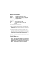
2 Locate and identify the two option Links 1 and 2. Use a pair of small wire cutters to cut the appropriate links to give the required configuration. 3 Cutting Link 1 will give a minimum temperature set point of 16°C (factory default is 5°C). Cut link 2 to display cooling symbol instead of heating symbol. 4 Replace batteries being sure to observe the correct polarities. Re-fit to plastic base and tighten retaining screw. Check unit is functioning as required.
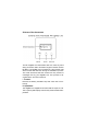
RF DigiMax 210 Rear View Link 2 Link 1 Batteries 3 2 1 Terminal block Cut Link 1 for 16°C minimum set point Cut Link 2 to display cooling symbol instead of heating symbol RF link between the Thermostat RF DigiMax 210 and the RF-Max a) Commissioning The RF DigiMax 210 is required to be matched with the RFMax receiver. This is to ensure only the correct thermostat is controlling your ambient temperature.
RF Receiver Led’s (indicators) : Red Led : ‘flashing’ : ‘steady on’ : indicates receiving an RF signal indicates a fault condition e.g. RF signal not being received ‘slowly plusing’ : indicates a valid install code has been received Green Led : ‘steady on’ : - indicates demand for heat ‘off’ : - no demand for heat i.e. heating call satisfied b) Checking the hard wired circuit : 1. Rely the RF-Max receiver to the mains. Check that no thermostat in the heating network request warm. The red LED should be off.
2. Within the 5 minute install period go to the RF-Max Receiver. Press and hold the Install button and then press the Test button while the Install button is held. This will clear out any previously installed codes. The Red Led will pulse slowly for 3 seconds to indicate this has been done. 3. Next, place the Receiver in Install mode by pressing and holding the Install button (for at least 10 seconds). The Red LED will come on and stay on until a valid Install Code has been received.
utes the Red LED will flash for 3 seconds. If the RF-Max does not receive regular RF signals the Red LED will come full on indicating that a fault condition has occured and the heating system will be switched off. Note : If more than one “Thermostat RF- RF Receiver” is installed with the same caracteristics, it is important to apply the above process for each thermostat, in order to be sure that each thermostat is connected to the right receiver. c) Trouble shooting 1.
4. Trouble shooting If the heater does not operate when the thermostat is asking for warm, check the battery indicator and changes the battery units if necessaru. If the indicator has vanished, remplace the piles for you have probably missed the signal indicating weak battery.
Extending the SC9000 security console with a Digimax 210 thermostat. The HF DigiMax 210 thermostat does not require extra wiring and has a radius of 30 m. The appliance is equipped with a protected HF code. This code is registered with the SC9000 during installation. This code ensures that the SC9000 will only respond to messages sent by your DigiMax 210. You can register up to 4 DigiMax 210 thermostats with the SC9000.
Extending the SC9000 security console with a Digimax 210 thermostat. If the console has not received any more messages from the thermostat, the LCD display will read [PROBLEM ZONE X] Programming the “differential temperature” on the console The thermostat needs to be registered with the SC9000 to be able to view the Setback settings in the OPTIONS menu (7). 1. To access the menu, press the menu Ĺ or menu Ļ button. The display will now read [ENTER PIN] 2. Enter your 4-digit PIN code (factory setting 0000.).