Dial Up Video Server Model: DGRT400 Installation / User Manual
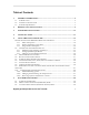
Table of Contents 1. GENERAL INFORMATION.......................................................................................... 5 1.1 1.2 1.3 INTRODUCTION................................................................................................................ 5 TECHNICAL SPECIFICATION............................................................................................. 7 SYSTEM REQUIREMENTS .................................................................................................
7. TROUBLESHOOTING ................................................................................................. 53 7.1 8. 4 HOW TO GET SOFTWARE UPDATES AND TECHNICAL SUPPORT ...................................... 53 WARRANTY PAGE………………………………………..………………….
GENERAL INFORMATION 1. GENERAL INFORMATION 1.1 Introduction Thank you for purchasing Digimerge product. The Dialup Video Server (DVS) will enable you to monitor sensitive locations and remote areas over standard phone lines. A key feature of DVS is the ability to not only visually survey a sensitive location, but to also hear what is occurring at the scene as well as speak to anyone at the monitored location.
GENERAL INFORMATION • Camera Pan/Tilt/Zoom (PTZ) control for certain camera models: SONY EVI-G20, SONY EVI-D30, KALATEL, PHILIPS TC-700 and DCP-1010 (Pelco-D) etc. • Can be optionally connected to Windows-based WWW server to make JPEG images available through the web browser. DVS will become an important part of your personal or corporate security video and audio surveillance system.
GENERAL INFORMATION 1.2 Technical specification • • • • • • • • • • • • • • 4 BNC composite video inputs (1 Vp-p/75 Ohm) One full duplex audio channel: Microphone/Linear and Speaker jack’s connectors provided for external electret-foil microphone and speaker. 2 RS-232 ports (male). One RS-232 is for external modem and another for PTZ function support. 8 inputs (TTL level) for external alarm sensors.
GENERAL INFORMATION • • Display adapter configured for 16-bit or better color mode (32768 or more colors) at 800x600 or higher resolution. 5 MB of free space on system hard disk are required for standard software installation. Additional free space is required to store individual still images and image sequences. The rest of this document contains important installation and operating instructions for DVS hardware (remote unit) and the client software on the operator’s PC.
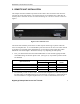
REMOTE UNIT INSTALLATION 2. REMOTE UNIT INSTALLATION This chapter describes installation procedure of the remote video surveillance unit that is the essential part of the DVS package. The remote DVS unit is a standalone device that does not need any direct connection to a PC on remote monitoring site. The unit’s exterior is shown in Figure 1. Figure 1 DVS unit front view The remote unit should be placed on the site that requires monitoring, anywhere within the reach of a telephone line.
REMOTE UNIT INSTALLATION Phone connector on the DVS. In that case, you may need to adjust (increase) the number of rings after which the DVS will respond to an incoming call in order to avoid conflicts with normal phone and/or fax usage and the associated inconveniences. See section 5.2.1 and Figure 7 on page 23 for more information on DVS configuration options. Note: • • The condition of the telephone line could be a reason for low modem connection rate and poor image transmission performance.
REMOTE UNIT INSTALLATION Figure 2 DVS unit rear view If all connections are properly made and the DVS start up process is completed successfully, proceed to the following chapters to learn how to install and use Digimerge DVS client software from your PC.
SOFTWARE INSTALLATION 3. SOFTWARE INSTALLATION The Digimerge DVS client software can be easily installed on any desktop or notebook PC running Windows 95, Windows 98, Windows Me, Windows NT 4.0, Windows 2000 or Windows XP operating systems that is equipped with an internal or external modem. The installation is done by simply double-clicking on the dm51xx.exe self-installable file (xx here is the version number). The install script will then proceed and you should follow the prompts as indicated.
UNINSTALLATION 4. UNINSTALLATION You can remove the Digimerge DVS client software from your computer at any time, if desired. The complete product uninstallation can be accomplished by doing one of the following actions: 1. Start -> Programs->Digimerge -> Dialup Video Server -> Uninstall 2. Re-execute the installation program dm51xx.exe (xx here is the software version number) 3. Launch the Windows Control Panel and then select the Add/Remove Programs icon.
USING THE CLIENT SOFTWARE 5. USING THE CLIENT SOFTWARE This chapter describes the Digimerge DVS client software, including all control elements related to video images, cameras, alarm sensors and output relays. After successful completion of software installation the main Digimerge DVS client program can be launched either from the Digimerge Dialup Video Server program group or by clicking on the DVS icon on the Windows Desktop.
USING THE CLIENT SOFTWARE Getting started with Digimerge DVS client program After clicking on the Digimerge icon to launch the DVS client program, the main screen, in its initial state will be shown below (Figure 3).
USING THE CLIENT SOFTWARE 5.1.1 Main control panel The Digimerge DVS main control panel provides an easy way to perform any operation with a remote unit. Each of the buttons are described in detail below. Displays the Establishing connection dialog and lets you connect to any of the available remote DVS units. Use the same button to break the connection. When connected, the control button changes.
USING THE CLIENT SOFTWARE 5.1.2 Getting initial images from the DVS Before you can get any images from the DVS unit, you need to establish a connection from your PC. Press the (Connect to remote unit) button on the main control panel. This will bring up the Establishing connection dialog as shown in Figure 4. Use the Phone number field to enter the telephone number assigned to the line connected on the remote DVS unit you are trying to access.
USING THE CLIENT SOFTWARE Note that, as you enter any telephone number in the dialog, it will be memorized automatically, so the next time you will not have to retype it again. Simply pull the list down by the small arrow button on the right to choose from the 10 most recently used numbers. You can remove unwanted telephone numbers from the list by pressing the Delete Phone Number button right above it. The password is required in order to prevent unauthorized access to the remote DVS unit.
USING THE CLIENT SOFTWARE DVS unit will automatically begin transmission of the first images using the last stored or the factory default settings. Loading progress bars at the top right corner of each image window will show a green progress indicator that will advance as the image data is being received. For use of camera auto detection, access the Image Properties dialog as described in section 5.2.1.
USING THE CLIENT SOFTWARE 5.1.3 Image window description Figure 6 shows all controls available from the image window. Include in/exclude from update image cycle Camera name Loading progress bar Loading time (sec) Alarm indicator Save image as JPG Save sequence as AVI Image Area Change window size Resize corner Image Brightness, Contrast, and Saturation settings Image quality Figure 6 Image window interface Images from all cameras are updated in cyclic mode by default.
USING THE CLIENT SOFTWARE check box in Image properties dialog (section 5.2.1 on page 22), then manually align all windows. Image windows can be moved within the application window, as you like. Adjust image settings: Brightness, Contrast, and Saturation using pop up sliders. The default values (middle values) work fine with most of color video cameras under regular day lighting conditions.
USING THE CLIENT SOFTWARE 5.2 Configuring the remote DVS unit The DVS configuration settings can be accessed by pressing the (Properties) button, after the connection is established, allowing you to access the property pages. Each DVS unit has its own individual configuration options, such as callback telephone number, time, etc. These parameters should be viewed or modified independently if more than one DVS unit is used.
USING THE CLIENT SOFTWARE Figure 7 Selecting image path, snapshot quality and other parameters The slider for the Snapshot quality allows you to adjust the quality of images captured to internal DVS memory by clicking on the image window. The same settings will be used for alarm snapshots made in callback mode and CompactFlash recording.
USING THE CLIENT SOFTWARE quality settings. The image size increases exponentially with higher quality, and can greatly lengthen transmission. Enable image window auto resize check box lets you disable the rearrangement of image windows inside of a main window, so you can apply your own position and size of image manually. These settings will be saved.
USING THE CLIENT SOFTWARE Figure 8 Specifying Callback mode properties 5.2.2.1 Configuring the alarm sensors The signals from magnetic, infrared or sensors of other type, installed on the doors, windows, or ceiling can be directly connected to DVS and used as trigger signals for alarm image capture and callback with or without video motion detection. Clicking the Configure sensors button in the Callback Properties dialog will display the Sensor controls and out alarms dialog shown in Figure 9.
USING THE CLIENT SOFTWARE There are two kinds of sensor state (see State field in Figure 9): • Normally Open - the non-signaled state of sensor input – HI, when sensor input is not connected or connected to digital HI level • Normally Closed - the non-signaled state of sensor input – LO, when sensor input is tied to the ground or digital LO level. By pressing the Restore to default button you can assign all alarms as Normally Open. A green sensor icon in the State field means signaled state - alarm.
USING THE CLIENT SOFTWARE You may specify the time the output relays will be toggled in the Relay toggling timeout field. The relays to be toggled are assigned in the Toggle Relays field. In the example in Figure 9, the output relays 0; 1 will be toggled for infinite and 5 seconds after, the sensor will alarm 0 and 1 respectively. You may clear all checked Toggle Relays checkboxes with the Clear button.
USING THE CLIENT SOFTWARE 5.2.3 Changing external modem parameters Note: This section is applicable to the external PSTN or ISDN modem users only. Use Direct cable connection (COM port) mode (see section 6.2) to setup this settings before entering Custom configuration (External modem) mode (see section 6.3). Figure 10.
USING THE CLIENT SOFTWARE modem initialization string that must be executed after the modem starts. There are, however, a few limitations: 1. The length of string should be less than 40 characters. 2. All characters should be typed in the same case. (either lower case or upper case) 3. Set the modem to digital communication mode (i.e. X0, X1, X2, X3, X4). 4. Some ISDN modems cannot accept commands ending with , characters. They may need only .
USING THE CLIENT SOFTWARE 5.3 Motion Detection Control The motion detection function of the DVS provides you with the ease and convenience of (Motion detection) button automatic monitoring from a remote location. Pressing the brings up the motion sensitivity control window shown in Figure 11. If you wish to use video motion detection, you can set the sensitivity level using the Motion threshold slider. You can test the sensitivity level. The Running man image will start to flash when motion is detected.
USING THE CLIENT SOFTWARE 5.4 Relays and sensors control Pressing the (Relays and sensors) button brings up the relay/sensors window shown in Figure 12. DVS can generate up to 4 relay output signals. You can turn relays on or off by pressing the Relay Out buttons. Do this, set-up the initial relay states. For sensors, a red color means an alarm state. Press any sensor button to bring up the dialog for configuring the alarm sensors (shown in Figure 9 on page 26).
USING THE CLIENT SOFTWARE 5.5 Internal image memory management Pressing the (Image memory) button or making snapshots by mouse clicking on an image window activates the DVS internal image memory window, shown in Figure 13. In the upper left corner there is a Filling image memory indicator. This allows you see how much memory you can still use for making snapshots. Using Preview allows you to either download the images or delete them without downloading.
USING THE CLIENT SOFTWARE Snapshot information (size in bytes, time) Downloading progress bar Snapshot Area Figure 14 Downloading snapshots Digimerge Dialup Video Server User’s Guide 33
USING THE CLIENT SOFTWARE 5.6 Controlling Pan, Tilt, Zoom, Focus of remote cameras Pressing the (PTZ control) button on the main control panel brings up the PTZ (Pan/Tilt/Zoom) window shown in Figure 15. Pressing the arrow button affects the camera position. The Kalatel Cyber Dome camera will perform directed movement when you keep the arrow button pressed. These positions can be saved as user defined template name. You can adjust the camera's position while monitoring the remote location at the same time.
USING THE CLIENT SOFTWARE Figure 18 Camera ID selection dialog Here is a list of PTZ cameras currently supported by the DVS software: • KALATEL (Cyber Dome) cameras • SONY EVI G20, SONY EVI D30 cameras • Philips TC700/TC8560 series protocol • DCP-1010 or CNB-PTD302 camera (PELCO-D protocol) Digimerge Dialup Video Server User’s Guide 35
USING THE CLIENT SOFTWARE 5.7 Audio stream control Pressing the (Audio control) button on the main control panel brings up a control window shown in Figure 19. From here you can control the incoming audio data from the DVS and outgoing voice audio to the DVS (G723.1compressed to 5.3 K bit per sec). A Red color square at the left top corner of each audio control button means an Enabled state. Note: DVS MIC IN is designed for an electret-foil microphone only, (not dynamic type).
USING THE CLIENT SOFTWARE When using the audio channel, take into consideration the following tips: 1. Do not set audio volume to extremely high values, it may cause voice intermodulation (worse quality). You should start from middle sliders positions. 2. Sometimes transmitted or received audio may appear choppy.