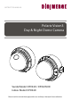
Polaris Vision3 Day & Night Dome Camera www.digimerge.com V2.
INSTRUCTION MANUAL Polaris Vision3 Day & Night Dome Camera Vandal Model: DPV34D / DPV24TLXR Indoor Model: DPD34D Please read this manual thoroughly before use and keep it handy for future reference.
-i-
-ii-
the -iii-
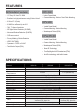
FEATURES All Models Feature: DPD34D • 1/3” Sony Ex-View™ II 960H • Indoor Dome Model • Excellent low light performance using Polaris Vision3 • Camera Mounting: Surface / Semi-Flush Mounting • 0.03Lux/F1.2 (Color) DPV34D • 0.
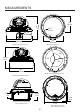
4.4" (112 mm) MEASUREMENTS 3.4" 87 mm Ø 0.1" 3.5 mm 3/4’’ -14 NPS thread 5.1" (130 mm) 3.9" 100.0 mm Vandal Dome Dimensions Base hole positions 100° 112 mm 4.4 in 137° 123° 5.1" 130 mm Underside Base hole positions Indoor Dome Dimensions 27 mm 1.1 in 39 mm 1.5 in 115 mm 4.5 in Indoor Dome Flush Mount Fitting dimensions Flush Mount Cutout and Fitting Clearance -2- 7 mm .
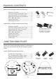
PACKING CONTENTS Indoor Dome package contains the following: Camera in housing----------------------------------1 Camera Locking screws (PA3 Type)------------2 Instruction guide (This Document)--------------1 Surface & Flush Mounting Templates----------2 RCA - BNC test cable-------------------------------1 Junction Box Plate-----------------------------------1 Mounting screw pack-------------------------------1 Locking Screw Conduit Key Allen Key Vandal Dome package contains the following: Camera in hou
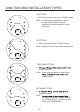
JUNCTION BOX INSTALLATION TYPES 2S FITTING a. 2S Fitting requires only 2pcs of 2S/4S screws. Screws Note: You have a reduced space in which to hide cables using this type of installation. Recommended for indoor dome only. Cable Entry 4S FITTING a. 4S Fitting requires 2pcs of 2S/4S screws. Note: Suitable for both indoor and vandal domes. Screws Cable Entry TWO GANG FITTING a. Screws of 2S/4S screws. Note: A two gang provides the most robust vandal domes. Cable Entry OCTAGON FITTING a.
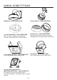
VANDAL DOME FITTINGS Wall Mount - model # MNTV2XW Pendant Mount - model # MNTV2XC Junction Box Mount - model # MNTV2XB Mount for either Vandal or Indoor Dome. Can also mount MNTV2XC or MNTV2XW. Pendant Cap - model # MNTV2XPC Replaces the need for the camera base. Compatible with ceiling conduit installations. Corner Mount bracket - model # MNTV2XR Can fit either MNTV2XW or MNTV2XJ. Pole Mount - model # MNTV2XP Can fit either MNTV2XW or MNTV2XJ.
INSTALLATION. VANDAL DOME ATTENTION - If using DC power, follow the correct polarity as marked on the power cable. 1 1) Loosen the three tamper screws using the provided allen key. Lift the dome cover. Note: If you plan to use conduit fitting, remove conduit cap using the provided conduit key. A B A Installation Option 1: Use holes marked with 'A' when installing camera base first. Use short 30mm screws and anchors.
INSTALLATION. VANDAL DOME 4 4) Remove camera cover by squeezing the back and front of the cover (as indicated by the arrow indicators) at the same time and lifting it up and away from the lens. Arrow 5 5) Insert the included video test cable into the RCA jack and connect to a test monitor to set up camera. Video test cable Zoom 6 Thumb Screw RCA Jack Focus 6a) Adjust camera viewing angle and secure into place by tightening thumb screw using a flat head screwdriver.
INSTALLATION. INDOOR DOME (Surface Mounting) ATTENTION - If using DC power, follow the correct polarity as marked on the power cable. 1 1a) Press down on the tab marked with an arrow to lift up the dome cover slightly b a 1b) While pressing on tab, twist the dome cover counter clockwise just a few degrees to release dome cover from back clips. Lift off the cover. Method 1 - Direct Attach Install 2 2a) Use included mounting template to mark and predrill the required holes. Use included 2.
INSTALLATION. INDOOR DOME (Semi-Flush Mount) ATTENTION - If using DC power, follow the correct polarity as marked on the power cable. 1 1a) Press down on the tab marked with an arrow to lift up the dome cover slightly b a 2 1b) While pressing on tab, twist the dome cover counterclockwise to release dome cover 1c)Remove the camera base by unscrewing the base locking screws (indicated by a padlock markings) and turn camera module approx.
CAMERA ADJUSTMENT RCA Service Connector Use supplied RCA - BNC cable If you require BNC output. OSD function joystick. Pressing down on joystick acts as ENTER function.
CAMERA ADJUSTMENT OSD MENU control Press down on the function joystick to access the setup menu. Joystick has 4 directional buttons. Press down on the middle of the joystick to select menu options. • Main setup menu is displayed on the monitor screen. SETUP MENU SETUP MENU EXPOSURE PICT ADJUST WHITE BAL WDR DNR DAY/NIGHT PRIVACY MOTION DET OTHERS EXIT AUTO ATW AUTO SAVE ALL Select functions by moving the joystick up and down. Move the joystick left and right to change setting values.
CAMERA ADJUSTMENT EXPOSURE SETUP MENU EXPOSURE PICT ADJUST WHITE BAL WDR DNR DAY/NIGHT PRIVACY MOTION DET OTHERS EXIT AUTO ATW AUTO SAVE ALL Changes the output exposure settings a choice of AUTO(default) or MANUAL.
CAMERA ADJUSTMENT MANUAL SETUP MODE SHUT AGC SHUT 1/60 (S) 6 (DB) RETURN • MANUAL MODE: SHUT / SLOW Lets you select combination of exposure modes. SHUT: When MODE is set to SHUT, select shutter speed in x / second 1/60 ,1/100, 1/250,1/500,1/1000,1/2000, 1/4000,1/10000 Default setting is 1/60 SHUT: When MODE is set to DSS The shut speed can be 2,4,8,16,32,64,128,256 Default setting is 2 AGC: Set a fixed gain value for the AGC db 6,12,18,24,30,36,42,44.
CAMERA ADJUSTMENT PICT ADJUST SETUP MENU EXPOSURE PICT ADJUST WHITE BAL WDR DNR DAY/NIGHT PRIVACY MOTION DET OTHERS EXIT Picture and display control settings AUTO ATW AUTO SAVE ALL PICT ADJUST MIRROR DIS EZOOM LEVEL SHARPNESS HUE R-GAIN B-GAIN OFF OFF 032 009 042 104 176 RETURN • MIRROR: • • DIS: EZOOM OFF/V-FLIP/H-FLIP/HV-FLIP Horizontally and vertically flip the display output. ON / OFF Enable/Disable Digital Image Stabilization.
CAMERA ADJUSTMENT ZOOM: PAN: TILT: 000-255 000-1023 000-512 Default 0 Default 512 Default 256 Note: Zoom must be higher than 0 to use Pan and Tilt settings. • LEVEL: 000-063 Screen brightness. • SHARPNESS: 000-015 Screen sharpness. • HUE: 000-100 Adjust the HUE value • R-GAIN: 000-255 Adjust the RED gain. • B-GAIN: 000-255 Adjust the BLUE gain.
CAMERA ADJUSTMENT ATW FRAME: ENVIRONMENT: x0.50 / x1.00 / x1.50 / x2.00 Sets pull in frame for magnification Default setting is X0.50 INDOOR / OUTDOOR Set the pull in frame of ATW Default setting is OUTDOOR • PUSH Use white balance regardless of the subject conditions.
CAMERA ADJUSTMENT WDR SETUP MENU EXPOSURE PICT ADJUST WHITE BAL WDR DNR DAY/NIGHT PRIVACY MOTION DET OTHERS EXIT Wide Dynamic Range. WDR SETUP MODE LEVEL HLC CLIP LEVEL SCALE BLC AUTO ATW AUTO SAVE ALL OFF OFF OFF 000 010 RETURN • MODE: OFF / D-WDR E: OFF / D-WDR D-WDR: Gamma curve, high & low luminance adjusted Default is Off HLC: OFF / ON / AUTO Highlight compensation. CLIP LEVEL: 000-255 Clipping level.
CAMERA ADJUSTMENT DNR DNR MODE LEVEL 3D LOW RETURN • DNR MODE: LEVEL: DAY/NIGHT 2D+3D / 3D / 2D / OFF Noise reduction Filter mode. OFF/LOW/MIDLOW/MID/MIDHIGH/HIGH Adjustment of the filter strength. Default setting is LOW AUTO / BW / EXT /COLOR SETUP MENU EXPOSURE PICT ADJUST WHITE BAL WDR DNR DAY/NIGHT PRIVACY MOTION DET OTHERS EXIT AUTO ATW AUTO SAVE ALL Day/Night mode can be set to the following options: COLOR/AUTO/EXT/BW.
CAMERA ADJUSTMENT • AUTO BURST: ON / OFF Selects whether to output the burst signal when night mode has been identified. 000-255 Night/Day identification transfer time. 000-255 Threshold for Night status from day status. 000-255 Threshold for the Day status from night status. DELAY CNT: DAY - NIGHT: NIGHT - DAY: • BW SETUP: Allows additional Smart IR settings to be enabled.
CAMERA ADJUSTMENT PRIVACY OFF / ON SETUP MENU EXPOSURE PICT ADJUST WHITE BAL WDR DNR DAY/NIGHT PRIVACY MOTION DET OTHERS EXIT AUTO ATW AUTO SAVE ALL Hide an area so that it is not displayed on the monitor. PRIVACY AERA SEL MODE POSITION COLOR TRANSP MOSAIC 1 / 15 OFF - RETURN AREA SEL: MODE: Select the privacy area to be adjusted. OFF / ON When ON the settings below can be changed Default OFF for all Areas PRIVACY AREA SEL MODE POSITION COLOR TRANSP MOSAIC 1 / 15 ON WHITE 1.
CAMERA ADJUSTMENT POSITION: When selected area selection screen appears: NEXT: PUSH ENTER Move the joystick to move the corners (you can create any 4-sided shape). The selected side is highlighted by a small box. To select the next corner, press ENTER. To return to privacy menu, press enter repeatedly. COLOR: BLACK, RED, GEEEN, BLUE, YELLOW, CYAN, MAGENTA, WHITE. Sets the colors of the mask frames. TRANSP: 1.00 / 0.75 / 0.50 / 0.00 Sets the privacy area transparency.
CAMERA ADJUSTMENT MOTION DET MOTION DET DETECT SENSE BLOCK DISP DETECT AREA MONITOR AREA OFF OFF 111 RETURN MOTION DET: DETECT SENSE: BLOCK DISP: DETECT AREA: OFF / ON. Turn on or off the motion detection. Default is OFF 0-127 Sets the motion detection sensitivity level. ON/OFF: Displays blocks in areas where motion is detected. Select area of the screen to enable / disable motion detection.
CAMERA ADJUSTMENT MONITOR AREA : Allows you to configure up to 4 motion detection areas. Areas will be highlighted on the screen and flash when motion is detected within them. Areas will not flash if motion is detected in areas that have been disabled using DETECT AREA. MONITOR AREA AERA SEL MODE TOP BOTTOM LEFT RIGHT 1/4 OFF 000 000 000 000 RETURN AREA SEL: 1/4, 2/4, 3/4, 4/4 Select area to adjust.
CAMERA ADJUSTMENT OTHERS SETUP MENU EXPOSURE PICT ADJUST WHITE BAL WDR DNR DAY/NIGHT PRIVACY MOTION DET OTHERS EXIT AUTO ATW AUTO SAVE ALL Miscellaneous camera functions. OTHERS LANGUAGE ENGLISH LENS AUTO SYNC INT CAM TITLE OFF WPC VERSION CAMERA RESET RETURN • LENS MANUAL / AUTO AUTO IRIS TYPE MODE SPEED DC AUTO 064 RETURN MODE: SPEED: AUTO,OPEN,CLOSE Sets the mechanical iris control mode. 000-255 Sets the convergence speed of the mechanical iris.
CAMERA ADJUSTMENT • CAM TITLE OFF / ON Select a camera title to be shown on the screen. CAMERA TITLE SETUP CAMERA ABCDEFGHIJKLMNOPQRSTUV WXYZ0123456789-!#$%&’ ()_`.:;<=> @^*./^*X+/ CHR1 CHR2 CLR POS RETURN Use Up/Down/Left/Right to move around. CLR will clear info. POS allows you to change the title position. • SYNC Camera uses internal sync (INT) when camera is connected to DC power. Line Lock (LL) is used when camera is connected to AC power.
CAMERA ADJUSTMENT • VERSION Gives version information regarding current camera software. VERSION INFO MCU VER ROM VER V1.0.0 NORMAL V1.0.0 RETURN • CAMERA RESET This will reset all settings for all menus to manufacturer defaults. EXIT / SAVE ALL SETUP MENU EXPOSURE PICT ADJUST WHITE BAL WDR DNR DAY/NIGHT PRIVACY MOTION DET OTHERS EXIT • AUTO ATW AUTO SAVE ALL EXIT Exit OSD menu. Exit will keep any changes only until camera is powered off.
TROUBLESHOOTING Follow the steps below if you are experiencing trouble with your camera. Contact Digimerge Technical Support if the issue persists. • Nothing appears on the screen. ¤¤ Check that the power cable is connected properly and that the voltage is correct. ¤¤ Check that you have properly connected VIDEO cable to the camera VIDEO output jack and to the monitor/DVR. • The image on the screen is unclear. ¤¤ Is the lens or dome cover stained with dirt? Clean lens or dome cover with soft, clean cloth.