DPZ36WO23 / DPZ36WO30 PTZ Camera Instruction Manual English Version 1.0 www.digimerge.com Copyright © 2012 Digimerge Technologies Inc.
CAUT I O N These servicing instructions are for use by qualified service personnel only. To reduce the risk of electric shock do not perform any servicing other than that contained in the operating instructions unless you are qualified to do so.
Contents Caution 4 IMPORTANT SAFETY INSTRUCTIONS 6 1. Overview 7 1.1 Features 7 8 8 guration 1.3 Termination Settings 2. Installation and Connection 2.1 Package Contents 2.2 Surface Mounting 2.3 Mounting Accessories 2.4 Connection Interface and Wiring Cables 2.5 Setting Dome Camera 3. Program and Operation 9 9 10 10 11 12 13 OSD Menu Structure 3.1 Getting Started 3.2 Main Menu 3.3 System Setup Menu 3.4 Display Setup Menu 3.5 Camera Setup Menu 3.6 Dome Motion Menu 3.7 Preset Setup 3.
Caution This device complies with Part 15 of the FCC Rules. Operation is subject to the following two conditions; 1. This device may not cause harmful interference. 2. This device must accept any interference received, including interference that may cause undesired operation. Note This equipment has been tested and found to comply with the limits for a Class A digital device, pursuant to part 15 of the FCC Rules.
Caution Correct Disposal of This Product (Waste Electrical & Electronic Equipment) (Applicable in the European Union and other European countries with separate collection systems) This marking shown on the product or its literature, indicate that it should not be disposed with other household wastes at the end of its working life.
IMPORTANT SAFETY INSTRUCTIONS 1) Read these instructions. 2) Keep these instructions. 3) Heed all warnings. 4) Follow all instructions. 5) Do not use this apparatus near water. 6) Clean only with dry cloth. 7) Do not block any ventilation openings. Install in accordance with the manufacturer’s instructions. 8) Do not install near any heat sources such as radiators, heat registers, ers) that produce heat. 9) Do not defeat the safety purpose of the polarized or grounding-type plug.
1. Overview 1.
1. Overview guration MULTI PLEXER 1.
2. Installation and Connection 2.1 Package Contents Camera Mounting Template Manual Screws / Plastic anchors / Allen Key / O-Ring Screws (#8(Ø4.
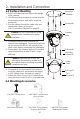
2. Installation and Connection 2.2 Surface Mounting 1 - Select a location that can support the weight of the camera. 2 - Use the mounting template to create holes for the mounting screws and cable. Insert the anchors(4). 3 - Run the cables through the cable hole and connect the cables as shown in {2.4.5 Connection Diagram} on page 11. Caution: Do not connect power to the camera before completing the entire installation. 4 - Remove the dome cover. Remove the internal foam packaging.
2. Installation and Connection 2.4 Connection Interface and Wiring Cables Caution Remove the protection sheet (PE form) before connecting power to the camera. Do not connect the power cable until all other connections have been completed. 2.4.1 Connecting the RS-485 lines The dome camera can be controlled remotely by an external device or control system such as a controller using RS-485 half duplexer (RS-485 Connection). A repeater is recommended to extend over 1.2km. 2.4.
2. Installation and Connection 2.5 Setting Dome Camera The device can communicate with external switching devices such as multiplexers or DVR’s by setting the Rotary switch and Dip switch. Refer to tables below for setting the dome camera ID and protocol selection. Total length of the cable for communication should not exceed 1km. 2.5.1 Setting the address (ID) of dome camera To prevent wrong operation and malfunction, each dome camera has a unique address (ID). The default setting is 0[ID001] .
3. Program and Operation [OSD Menu Structure] - Main Menu/Editing Title MAIN MENU TITLE SYST EM SET U P D I SPLAY SET U P C AMER A SET U P D O ME MO T I O N PR ESET SET U P PAT T ER N SET U P T O U R SET U P SC AN SET U P ALAR M SET U P EXIT - Operation Menus X23(X30) MINI SPEED DOME V x.xx.xx RS485/2400 ID001 NTSC 13 ABCDEFGHIJKLMNOPQRSTUVWXYZ 0123456789/+-=:?!#.
3.
3.
3. Program and Operation 3.1 Getting Started Before installing and operating the dome camera, please read this Instruction Manual carefully. This dome camera can be operated using two methods: - Use hot keys [See Appendix] - Use OSD Menu on the monitor You should install and connect the dome to an interface device before using this operating guide. See [2. Installation and Connection]. Once installed, apply power to the dome. The start-up screen is displayed on the monitor.
3. Program and Operation 3.2.2 Editing TITLE TITLE ABCDEFGHIJKLMNOPQRSTUVWXYZ 0123456789/+-=;?#.,"~0 SELECT : (MOVE) SET/CLEAR: (TELE/WIDE) SAVE : (NEAR) EXIT : (FAR) The Title edit menu can be used in the setup titles for Presets, Patterns, Tours, and Scans. - Select {Title} in the appropriate menu and move the joystick to the right. - Move the joystick right, left, up or down to select a character. - Press [Tele] button to input a character and [Wide] button to cancel the character.
3. Program and Operation 3.3.2 Reboot REBOOT CONTINUE? YES : N EAR NO : FAR Reboot the system if operation becomes unstable or encounters errors. Rebooting the system will turn the camera on and off without changing settings. - Enter into {Main Menu} - Select {System Setup} then {Reboot} using the joystick. - To {Reboot} the system, press the [Near] key. - To cancel, press [Far] key. 3.3.
3. Program and Operation 3.3.4 Entering a Password * Note: 0000 is the default password. PASSWORD C U R R EN T ENABLE N EW CONFIRM : : : : ... DISABLE ... ... 0123456789 -SET / C LEAR : (T ELE/ WI D E) -EXI T : (F AR ) To prevent unauthorized changes to settings, you can enable password protection. When password protection is enabled, you must enter the password to enter the Main Menu. Passwords must be 4 characters long.
3. Program and Operation 3.4.2 OSD Setup OSD SETUP - TITLE LA B E L P O S I T I O N : O F F T I ME : ON ZOOM : OFF ID : ON MO D E : ON A N G LE : 3SEC SAVE : O PEN BACK : CLOSE - CHANGE : (LEF T / R I G H T ) - TO SETUP : (T ELE) ER R O R MSG - EXIT : FAR ZOOM - MODE - D T I ME - ID - AN G LE - OSD setup allows you to program how labels are displayed on the monitor. Labels can be configured for Title, Dwell Time, Zoom ratio, Camera ID, Operation Mode and PTZ Angle. Label position can be adjusted.
3. Program and Operation 3.4.4 Image Setup IMAGE SETUP MI R R O R : N O R MAL SAVE BAC K : O PEN : C LO SE This menu allows you to mirror the image horizontally, vertically, or both. - Enter into {Main Menu} - Select {Display Setup} and then select {Image Setup} using the joystick[ ]. - Highlight {Mirror} and select Normal, Horizontal, Vertical, or H/V (Horizontal and Vertical).
3. Program and Operation 3.5 Camera Setup Menu CAMERA SETUP F O C U S/ Z O O M W-BALANCE EXPO SU R E D AY/ N I G H T ADVANCE WDR/DNR EXIT / : move joystick up and down to select items. / : move joystick left and right to change settings. / [Open]/ [Near]: move joystick right to enter sub-menus. / [Close]/ [Far]: move joystick to cancel or to exit current menu without saving changes. 3.5.1 Focus/Zoom FOCUS/ZOOM SETUP FOCUS : AU T O Z O O M SPD : V-F AST D.
3. Program and Operation 3.5.3 AE Setup (Auto Exposure Setup) AE SETUP MO D E SHUT AG C G AI N AG C MAX D SS BR I G H T : : : : : : F U LL AU T O HIGH OFF 06 SAVE : O PEN BAC K : C LO SE Shutter speed is the duration of the electronic shutter. Set the shutter speed to operate automatically (Full Auto) or manually (Numeric Value). . The AGC (Automatic Gain Control or AGC Max Gain) adjusts the brightness of the picture. The brightness increases as the number gets higher.
3. Program and Operation 3.5.5 Advanced Setup ADVANCED SETUP SH AR PN ESS BAC KLI G H T : 10 : OFF SAVE : O PEN BAC K : C LO SE The Backlight Compensation function increases the brightness of the overall screen to compensate for a loss of dark detail when subjects are shot in a backlit environment. Sharpness enhances picture detail by increasing the aperture gain of the camera and sharpening the edges in the picture.
3. Program and Operation 3.6 Dome Motion Menu DOME MOTION SETUP G EN ER AL SET U P MOTION SETUP H O ME AC T I O N C ALI BR AT I O N EXIT / : move joystick up and down to select items. / : move joystick left and right to change settings. / [Open]/ [Near]: move joystick right to enter sub-menus. / [Close]/ [Far]: move joystick to cancel or to exit current menu without saving changes. 3.6.1 General Setup GENERAL SETUP PO WER -U P AC T .
3. Program and Operation 3.6.2 Motion Setup MOTION SETUP PR O P. PAN / T I LT AU T O F I LP OVER TILT : ON : ON : MODE 1 SAVE : O PEN BAC K : C LO SE Proportional Pan/Tilt (Prop. Pan/Tilt) adjusts the manual pan/tilt speed according to the zoom level. - Highlight {Prop. Pan/Tilt} and use the joystick to select On/Off. Auto-Flip automatically reverses the image when the camera passes the top of the tilt arc (90 degrees).
3. Program and Operation 3.6.4 Calibration Setup C O N T I N U E? CALIBRATION SETUP YES : N EAR NO : FAR A U T O C A L : AU T O E R R O R MS G D I SP : O F F C A LI B R A T I O N SAVE : OPEN B A C K : C LO S E Calibration allows you to correct Pan/Tilt control errors. - Enter into {Main Menu}. - Select {Dome Motion} and then select {Calibration} using the joystick [ ]. - Highlight {Auto Cal} and select Auto for Auto Calibration or Manual for Manual Calibration.
3. Program and Operation 3.7.1 Saving Presets PRESET SETUP PRESET SETUP N O . 001 EDIT T I T LE D T I ME C LE A R PR ESS MO VE KEY : N OT U SED : : : SAVE : N EAR BACK : FAR SAVE : OPEN B A C K : C LO S E - Enter into {Main Menu} - Select {Preset Setup} using the joystick [ ]. - Highlight {No.} and move the joystick left and right to select the preset you would like to edit. - Select {Edit} to edit the preset. Use the joystick to move the camera into the desired position and press [Near] to save.
3. Program and Operation Use the following steps to program a Pattern. PTIME: 022 START POSITION SETUP PATTERN SETUP PATTERN SETUP N O . 001 : N O T USED EDIT : T I T LE : TIME : C LE A R PR ESS MO VE KEY ST AR T : (N EAR ) SAVE : (NEAR) EXI T : (F AR ) SAVE : OPEN B A C K : C LO S E - Enter into {Main Menu}. - Select {Pattern Setup} using the joystick [ ]. - Highlight {No.} and select the number of the pattern you would like to edit. - Select {Edit} to edit the pattern.
3. Program and Operation 3.10 Auto Scan Setup SCAN SETUP NO. 001 : NOT USED ED I T : SPEED : DTIME : D I R EC T I O N : MO D E : C LEAR SAVE : O PEN BAC K : C LO SE / : move joystick up and down to select items. / : move joystick left and right to change settings. / [Open]/ [Near]: move joystick right to open sub-menus. / [Close]/ [Far]: move joystick to cancel or return to previous menu without saving changes.
3. Program and Operation 3.11 Alarm Setup The Alarm Setup menu allows you to configure alarm inputs and outputs. ALARM SETUP N O . 001 : N O T U SED IN : OUT : PR I O R I T Y : AC T I O N : N U MBER : A T I ME : SAVE : O PEN BAC K : C LO SE - SET / C LEAR : (T ELE/ WI D E) / : move joystick up and down to select items. / : move joystick left and right to change settings. / [Open]/ [Near]: move joystick right to ener sub-menus.
4. Troubleshooting Guide If problems occur, please consult the following steps before contacting Digimerge Technical Support. Problem No video on the screen Poor video quality.
cations (DPZ36WO23) Image Device 1/4" Sony Double Scan, Super HAD CCD II Effective Pixels NTSC: 976(H)*494(V) Resolution 600 TVL Lens 23X Optical /10X Digital Zoom(Auto Focus) View Angle Approx. Approx.58.1° (Wide end) to 2.8° (Tele end) Min. illumination 0.2 Lux/ F1.6, 0.001 Lux/DSS, 0.1 Lux/ICR S/N Ratio More than 52dB WDR On/Off DNR 3DNR Privacy Masking Max.
cations (DPZ36WO30) Image Device Effective Pixels Resolution Lens View Angle Approx. Min. illumination S/N Ratio WDR DNR Privacy Masking Electrical Power Supply Power Requirement Power Consumption 1/4" Sony Double Scan, Super HAD CCD II NTSC: 976(H)*494(V) 700 TVL 30X Optical /10X Digital Zoom(Auto Focus) Approx. 69.5° (Wide end) to 2.46° (Tele end) 0.2 Lux/ F1.65, 0.001 Lux/DSS, 0.1 Lux/ICR More than 50dB On/Off 3DNR Max. 15 zones AC24V (±10%) Normal, Built-in Power Line Surge Adapter AC24VAC, 2.
6. Dimensions [Unit: mm] 26 79 138 Ø112 Ø151.3 Ø154 85.6 4-Ø4.8 85.
APPENDIX. Pelco Protocol Function List LCD DISPLAY Function Keys > F1(PSET), F2(TOUR), F3(PATT), F4(SCAN) ESC/POWER Joystick Number Controller Function Keys Camera Focus control > NER / FAR, TELE / WIDE Based on WTX1200A Function Preset Preset shortcut saving Run PAN Run PAN ZERO Scan Setup Scan Tour Setup Tour Pattern Setup Pattern MENU Key ESC Key D. Zoom (Toggle) Key Preset Preset No.
DPZ36WO23 / DPZ36WO30 English Version 1.0 www.digimerge.com Copyright © 2012 Digimerge Technologies Inc.