2.0 Megapixel H.264 Network IP Camera User Manual Product: BLK-IPS102M Please read this manual before using your camera, and always follow the instructions for safety and proper use. Save this manual for future reference.
WARNING RISK OF ELECTRIC SHOCK. DO NOT OPEN. To reduce the risk of electric shock, do not remove cover (or back). No user serviceable parts inside. Refer servicing to qualified service personnel. CAUTION Operate this camera only in environments where the temperature or humidity is within the recommended range. Operation in extreme temperatures or humidity levels may cause electric shock and shorten the life of the product.
Table of Contents SECTION 1 SECTION 2 SECTION 3 APPENDIX A APPENDIX B APPENDIX C Features. . . . . . . . . . . . . . . . . . . . . . . . . . . . . . . . . . . . . . . . . . . . . . . . . . . . . . . . . . . . . . . . . . . . . . . . . . . . 2 Installation and Setup. . . . . . . . . . . . . . . . . . . . . . . . . . . . . . . . . . . . . . . . . . . . . . . . . . . . . . . . . . . . . . . . 4 2.1 What’s in the box . . . . . . . . . . . . . . . . . . . . . . . . . . . . . . . . . . . . . . . . . . . . . .
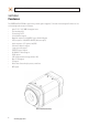
SECTION 1: FEATURES SECTION 1 Features The DIGIOP Black BLK-IPS102M is a professional, premium-grade 2 megapixel, CS-mount box camera designed for indoor use. Lens and mounting bracket are optional. It features: • • • • • • • • • • • • • • • • • Aptina™ 1/3.2” (4:3) CMOS 2.0 megapixel sensor Dual streaming mode De-interlacing on DSP Unicast/multicast support Megapixel compression: H.264/MPEG-4, up to 1600 x 1200 pixels Video compression: H.264/MPEG-4/MJPEG (dual stream @ D1) Audio compression: G.
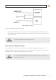
SECTION 2: INSTALLATION AND SETUP Reset USB connector DC jack adapter cable connector 9-pin terminal block LAN connector Micro SD card slot Back connectors Reset – For restarting the camera, or resetting the camera to its factory default network settings. Refer to Appendix A, Troubleshooting, for more information.
SECTION 2: INSTALLATION AND SETUP SECTION 2 Installation and Setup 2.1 What’s in the box Your camera includes the following: • • • • • • • • • BLK-IPS102M camera Cap for protecting the sensor DC power adapter with power plugs for different powering sources DC jack adapter cable Adapter for mounting the camera 9-pin terminal block Hex wrench Quick installation guide CD mini disk with application software, software manual, and camera manual (this document) 2.
SECTION 2: INSTALLATION AND SETUP 2. Install the camera mounting bracket using the instructions provided with the bracket. 3. Attach the adapter for mounting the camera to the side with the label or to the opposite side with the screws provided. Mounting adapter 4. Remove the protective cap covering the camera CCD. 5. Attach the lens assembly to the camera by screwing it clockwise onto the camera until it is fully seated. The lens may require a mounting ring adapter to fit onto the camera.
SECTION 2: INSTALLATION AND SETUP 6. Tighten the lens set screw with the hex wrench provided. 7. Attach the camera to the mounting bracket. Use the instructions provided with the bracket. 2.4 Connections Connections to the camera for audio in and out (microphone and speaker), DI sensor, DO alarm, and RS‑485 control are made through the 9-pin terminal block.
SECTION 2: INSTALLATION AND SETUP Audio in/out wiring schematic To connect a speaker and/or microphone to the camera: 1. Strip 1/4” of insulation from the microphone and speaker wires and insert them into the terminal block in the pin locations shown in the terminal block figure above. Note that the common (ground) leads of the microphone and speaker share the same terminal block pin. CAUTION Do not attach a headphone or earphone directly to the camera. 2.4.
SECTION 2: INSTALLATION AND SETUP Voltage type sensor wiring schematic Relay type sensor wiring schematic To connect a sensor to the camera, strip 1/4” of insulation from the sensor wires and insert them into the terminal block in the DI 1 and C pin locations shown above. The pin marked C in the terminal block is the common (COM) pin. 2.4.3 Alarm out (DO) connection The camera supports one alarm out connection to relay type device. It provides up to 24 VAC @ 500 mA or 12 V DC @ 1 A.
SECTION 2: INSTALLATION AND SETUP Relay type alarm wiring schematic To connect an alarm reporting device to the camera, strip 1/4” of insulation from the alarm wires and insert them into the terminal block in the DO 1 and C pin locations shown above. The pin marked C on the terminal block is the common (COM) pin. 2.4.4 RS-485 device connection The camera provides one RS-485 interface connection. The wiring signal polarity to the connector block is shown in the schematic below.
SECTION 2: INSTALLATION AND SETUP 1. Attach a LAN cable to the Ethernet connector on the back of the camera. If the camera is powered through the LAN cable, DO NOT apply power to the camera at this time. 2. Attach the DC jack adapter cable to the DC 12V power adapter terminals on the back of the camera. Connect the red wire of the adapter cable to the + terminal, and the black (or white) wire to the - terminal. DC jack adapter cable 3. Attach the DC jack Adapter to the DC power adapter provided.
SECTION 2: INSTALLATION AND SETUP 3. Copy the IPAdminTool directory with its contents to your computer hard drive. 2.6 Configure the camera network settings Devices attached to a Local Area Network (LAN) are each assigned a unique address (IP address) that they use when sending messages with each other. No two devices on a single Ethernet network can have the same IP address. Otherwise, addressing conflicts will occur.
SECTION 2: INSTALLATION AND SETUP Check the list of IP devices found by IPAdmin Tool. You can identify your camera by the MAC address. If the camera was not found, click the Refresh button every minute until your camera appears in the list. 3. In the IPAdmin Tool device list, use the camera’s MAC Address to find the camera you are installing. After finding the camera, right click the entry, then select IP Address from the drop-down list. An IP Setup window will open. 4.
SECTION 2: INSTALLATION AND SETUP If you have other compatible, network settings you want to apply to the device, enter them in the appropriate locations. Click Setup to save settings. 5. In the Login window, enter the ID and PW (password) for your camera and click Login. The default administrator values for the ID and PW are root and pass. After entering ID and PW, the IP Setup window closes. 6.
SECTION 2: INSTALLATION AND SETUP b. Type cmd in the entry field, then click OK to open the DOS command window. c. At the command prompt, enter ipconfig. The response will show the your PC’s network settings. Example: Typical use of ipconfig in Windows XP d. Enter the IP Address, Subnet Mask, and Default Gateway for your PC’s Ethernet adapter into Table 1. NOTE The Ethernet adapter data you see by using ipconfig will probably be different from that shown in the example above.
SECTION 2: INSTALLATION AND SETUP Find network settings (IP addresses) that are not in use 1. At your PC, find an IP address on your network that is not in use: a. Write down the EXACT IP address of your PC up to the third/last period. Using the example shown above, this expression is: 192.168.1. b. After the third period, include any number between 1 and 254 that is different from the one in your PC’s IP address, 168. As a first try, let’s choose 200, which will form the IP address 192.168.1.200. c.
SECTION 2: INSTALLATION AND SETUP e. In this test, the message “Request timed out” indicates that your PC cannot reach the device with that IP address, and that address is probably not in use. Enter this number into Table 1. If this test indicated that this IP address is in use, try other IP addresses using the steps above until an unused address is found. Check LAN for default IP address compatibility Because all DIGIOP Black cameras and encoders are factory configured with the static IP address 192.
SECTION 2: INSTALLATION AND SETUP 2. In the Product list, find the entry with the same MAC address as the camera you installed. If the camera is not shown, click Refresh once a minute to update the list. 3. Right click on the entry for your camera and select IP Address. IP Setup window 4. 5. In the IP Setup window: a. Select the Static option if it is not selected.
SECTION 2: INSTALLATION AND SETUP 6. In the IPAdmin Tool window, click Refresh and verify that the entry representing the camera now shows the new IP address. 7. In the IPAdmin Tool window, click Refresh and verify that the entry for your camera now shows the new IP address. 2.7 Setup the camera Basic Configuration In this procedure, Microsoft Internet Explorer (IE) browser is used to setup the camera administrator and user passwords, date, and time. 1. Open the IE browser. 2.
SECTION 2: INSTALLATION AND SETUP Typical initial camera view NOTE If, after logging into your camera, you cannot see live video and the message: “Can not Create XMLDOMDocument Install MSXML4.0” appears, download and install the MS XML 4.0 library. This library can be found at: http://www.microsoft.com/downloads/details.aspx?familyid=3144B72B-B4F2-46DA-B4B6-C5D7485F2B42&displaylang=en 4. In the camera window, click the SETUP link in the upper right corner of the window.
SECTION 2: INSTALLATION AND SETUP b. Select the synchronization method, or Set Manually bullet and enter the appropriate information. c. Select the Sync Source and Interval you prefer. d. Click Apply. 6. In the Basic Configuration menu, click Users. 7. In the User List, click root, and then click Modify and follow the prompts. Setup the root user with a new password and click OK. 20 www.digiop.
SECTION 2: INSTALLATION AND SETUP 8. In the Users menu, click Apply, then click OK to restart the webserver (if you wish to do so at this time). 9. Click Add to include other administrators, operators or viewers to the user list. Follow the screen prompts to complete the entries. 10. Click VIEW in the upper right corner of the window to return to the camera live view. 2.
SECTION 2: INSTALLATION AND SETUP 2. Scroll to the bottom of the screen and click the PREVIEW button. Follow the screen instructions to open the camera view in another IE window. 3. While observing the video in the PREVIEW window, adjust the values for brightness, contrast, hue, saturation, sharpness, and/or other parameters on screen. Click Apply to see the effect of the change. Make any necessary adjustments to produce the best video image. 4.
SECTION 2: INSTALLATION AND SETUP 2. In the Bi-directional Audio Settings menu, click the checkboxes to select “Listen to the audio from server with setting below” and “Talk to the speakers of server”. 3. Click Apply, and then click VIEW to return to the camera view screen. 4. On the VIEW screen, check the SPK and MIC options to enable the speaker at the camera and the microphone on your computer. 5. At your computer, listen for sounds from the microphone at the camera.
SECTION 2: INSTALLATION AND SETUP 2.10 Cleaning Clean the camera housing with an approved glass cleaning solution and a lint free cloth. • • Dust can be removed from the unit by wiping it with a soft damp cloth. To remove stains, gently rub the surface with a soft cloth moistened with a mild detergent solution, then rinse and dry it with a soft cloth. Remove all foreign particles, such as plastic or rubber materials, attached to the camera housing. These may cause damage to the surface over time.
SECTION 3: SPECIFICATIONS SECTION 3 Specifications Table 2. Specifications Camera Module Image Sensor Aptina (Micron®) 1/3.2” (4:3) CMOS 2M Effective Pixels 1600 x 1200 (UXGA, 2M) Scanning system Progressive scan Dynamic Range 71 dB SNR Max 42.3 dB Minimum Illumination 0.5 Lux (50 IRE), 0.1 Lux (DSS x5 ON) Lens (Optional) CS mount Day & Night S/W Video Megapixel Compression H.264 and MJPEG Compression Format H.
SECTION 3: SPECIFICATIONS Protocol TCP/IP, UDP/IP, HTTP, RTSP, RTCP, RTP/UDP, RTP/TCP, SNTP, mDNS, UPnP, SMTP, SOCK, IGMP, DHCP, FTP, DDNS, SSL v2/v3, IEEE 802.1X, SSH USB 2.0 Support (Mini-B plug) SD slot Supported (microSD type, not included) Electrical Characteristics Audio input Line-in, 1.43 Vp-p (min 1.35 Vp-p, max 1.49 Vp-p), 39 KΩ Audio output Line-out, 46 mW Power, 16 Ω Sensor (D/I) TTL level 4.
SECTION 3: SPECIFICATIONS Table 4. Video Content Analysis (optional)* VCA Presence High Performance Advanced tracking algorithm, low false alarm rate Easy to Use Intuitive web browser interface Detection Zones Multi-segment polygons and lines On-screen Display Real-time display of tracking data and events Burnt-in Annotation Stream Image Stabilization Electronic Stabilization Removes camera sway * Other VCA options are available. Call for details. 2.0 Megapixel H.
APPENDIX A: TROUBLESHOOTING APPENDIX A Troubleshooting A.1 Reboot camera NOTE The reboot process lasts about 2 minutes, during which time the camera will not respond to the IPAdmin Tool or transmit video to a web browser The camera can be rebooted in two ways: • • Using the IPAdmin Tool: a. Start the IPAdmin Tool. b. Find the entry for the camera you want to reboot and click it to select (highlight) it. c. Click the Reboot button and enter the administrator ID and PW. d.
APPENDIX A: TROUBLESHOOTING To force the camera to the factory network settings: 1. Disconnect the power (adapter) from the camera. 2. While pressing and holding down the reset button, power on the camera. 3. Release the Reset button 5 seconds after applying power. 4. Wait for the camera to reboot. A.3 Checking your Firmware Firmware is software embedded in the camera that determines many of its features and functionality.
APPENDIX B: POWER OVER ETHERNET APPENDIX B Power over Ethernet The BLK-IPS101 camera supports Power over Ethernet (PoE) in conformance with the IEEE 802.3af standard. IEEE 802.3af allows for two power options for Category 5 cables. The PoE module signature and control circuit provides the PoE compatibility signature and power classification required by the Power Sourcing Equipment (PSE) before applying up to 15 W power to the port.
APPENDIX C: DIMENSIONS APPENDIX C Dimensions 2.0 Megapixel H.