Digiplex Control Panel (DGP-848) - V4.
Table of Contents Features ................................................................................... 1 Specifications ........................................................................... 1 Ring-back............................................................................... 21 Switch To Stay Arming .......................................................... 21 Always Force Arm When Regular Arming ............................. 21 Installation..............................................
Power Save Mode ................................................................. 37 Auto Trouble Shutdown ......................................................... 37 No AC Fail Display................................................................. 37 Access Codes ................................................................ 38 Installer Code......................................................................... Access Code Length..............................................................
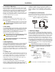
1 Introduction Paradox Security Systems has once again redefined the boundaries of the security industry and is proud to introduce the Digiplex control panel. A new generation in control panel technology, the Digiplex control panel uses a quad-wire combus that provides power and two-way communication for up to 95 modules (keypads, motion detectors, expansion modules, etc.).
2 Installation 2.1 Location & Mounting Before mounting the cabinet, push the five white nylon mounting studs into the back of the cabinet. Pull all cables into the cabinet and prepare them for connection before mounting the circuit board into the back of the cabinet. Select an installation site that is not easily accessible to intruders and leave at least 2" around the panel box to permit adequate ventilation and heat dissipation.
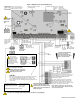
Figure 3: Digiplex Control Panel PCB Layout Four pin connector can be used for quick installation of a Digiplex keypad or module. Charging and battery test LED (every 64 seconds) “STATUS” LED: Short flash Long flash Constant OFF = Panel OK = TLM Fault = Dialer on-line = Panel error/off-line Reset jumper Warning: Disconnect the battery before replacing the fuse. Warning: Disconnect telephone line before servicing Optional connector can be used to recharge another battery in the system.
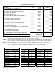
2.8 Calculating Power Requirements Table 1: Milliamp Consumption Table Description QTY.
Figure 4: Sample Power Requirement Calculations CONTROL PANEL = 700mA 16.5VAC 40VA Transformer AUX. OUTPUT Power required by devices connected to control panel’s auxiliary output must not exceed the auxiliary output’s limit: (A) + (B) + (C) + (D) + (E) + (F) + (G) + = 455mA<700mA = OK 15m (50ft.) 61m(200ft.) LCD Keypad (DGP2-641BL) (D) = 110mA Magellan Module (MG-RCV3) (A) = 35mA 7.5m(25ft.) Motion Detector Module (DGP2-70) (E) = 30mA 15m (50ft.) APR3-ZX8 (B) = 30mA 7.5m(25ft.) 30m(100ft.
2.9 Programmable Outputs The Digiplex control panel comes standard with PGM1 and PGM2. PGM3 to PGM5 are optional. When a specific event or condition occurs in the system, a PGM can be programmed to reset smoke detectors, activate strobe lights, open/close garage doors and much more. For details on how to program the PGMs, refer to section 10 on page 30.
2.12 Double Zone Connections 2.13 Keypad Zone Connections Enabling the ATZ feature (see section 4.8 on page 16) allows you to install two detection devices per input terminal. The ATZ feature is a software oriented feature. Simply connect the devices as shown in Figure 8. Devices connected to input terminals must be assigned to a zone and the zone's parameters must be defined. Please refer to Zone Programming on page 11. for more information. For UL listed installations, use EOL resistor part #2011002000.
smoke detector sends a CleanMeTM signal, the control panel will generate a Zone Fault trouble and if programmed will transmit the Fire Loop report code to the monitoring station. The trouble will be cleared if there is no CleanMeTM signal for 255 seconds. If an alarm occurs, the trouble will be cleared until it is detected again. Figure 10: PGM1 2-wire Smoke Detector Input PGM1 becomes input #255 When using ESL smoke detectors with the CleanME™ feature, do not connect more than 20 detectors in parallel.
3 Programming Methods The Digiplex control panel can be programmed using the WinLoad software, the Paradox Memory Key, or manually by using an LCD (DGP2-641BL) or Grafica (DNE-K07) keypad. We highly recommend programming the control panel with WinLoad as it greatly simplifies the process and reduces potential data errors. Please refer to WinLoad Software on page 44. for details on how to set up the control panel to function with WinLoad.
3.6 Level Programming Download to DESTINATION Control Panel: In the sections requiring Level Programming, only one option can be selected. 1) For LCD keypads: To select the option, use the [S] and [T] keys until the desired option is visible and then press [ENTER] to save. For Grafica keypads: To select the option, use Grafica’s scroll keys until the desired option is visible and then press Grafica’s center action key (Save) to save. 2) 3) (keyswitch serial numbers) from the key to the panel.
4 Zone Programming All detection devices connected to the control panel, keypads and zone expansion modules must be assigned to a zone and that zone must be defined as described in this section: Zone Numbering [001] to [048]: • Serial number of the device/module • Input number of the device/module Zone Parameters [101] to [148]: • Zone Definition • Zone Partition Assignment • Zone Options The Zone Numbering feature is used to individually assign each detection device to any desired zone in the Digiplex sy
4.1 Zone Numbering 4.2.2 Entry Delays 1 to 4 SECTIONS [001] TO [048] The Zone Numbering feature allows you to assign any detection device in the system to any of the 48 zones. This feature tells the control panel where the device is connected and which of the 48 zones is assigned to that device (Figure 14 on page 12). • To assign an addressable detection device connected to the combus, program the detector's serial number into the section corresponding to the desired zone (i.e.
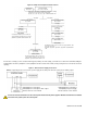
Figure 15: Delayed 24-hr. Fire Zone Figure 16: Bell/Siren Output During Fire Alarm Delayed Fire Zone Triggered Activate bell/siren output & delay report transmission for 30 seconds. 4.2.9 Stay Delay Zone Has the zone closed within 30 seconds? Yes No Has a 2nd Delayed Fire Zone opened in 30 sec.? Yes Latch alarm and transmit report code as described in the section "Standard 24Hr. Fire Zone". No Any key on keypad pressed within 30 seconds? No Yes Yes Bell/siren silenced.
4.4.2 Bypass Zones SECTIONS [101] TO [148]: OPTION [2] Only zones with option [2] enabled can be Manually Bypassed (see section 13.5.3 on page 39). Fire Zones cannot be bypassed. All zones are set as Bypass Zones by default. 4.4.3 Stay Zones SECTIONS [101] TO [148]: OPTION [3] Only zones with option [3] enabled will be bypassed when the system is Stay or Instant armed (see section 16.1.2 on page 45). All other zones will remain activated. Fire Zones cannot be set as Stay Zones. 4.4.
Table 5: Hebrew Keypad Letter Assignment Table 8: Hebrew Special Characters Catalogue Table 6: Russian Keypad Letter Assignment Table 7: Special Characters Catalogue Table 9: Russian Special Characters Catalogue DGP-848 Control Panel 15
4.6 Input Speed SECTIONS [201] TO [216] (000 to 255 X 20msec,default: 600ms) The Input Speed defines how quickly the control panel will respond to an open zone detected on any hardwired input terminal. The control panel will not display and/or respond to an open zone until the programmed Input Speed elapses to prevent glitches from causing an alarm or unnecessary reporting. All other zone definitions and options do not come into effect until the Input Speed has elapsed.
5 Keyswitch Programming The Digiplex control panel can support up to 8 keyswitch zones in addition to the 48 standard zones. A keyswitch allows a user to arm or disarm a system by pressing a key or by toggling a keyswitch. The keyswitches are connected to the hardwired input terminals of either the Digiplex control panel, zone expansion modules or the keypad. For more information on the installation of keyswitches, please refer to section 2.14 on page 7.
Figure 19: Example of Keyswitch Numbering 5.2.5 Generates a Utility Key Event on Open and Close SECTIONS [149] TO [156]: SECOND DIGIT = 4 When option [4] is enabled, a Utility Key Event will be generated whenever the keyswitch input is opened or closed. As a result, the Utility Key Events increase from 32 to 64 events when option [4] is enabled; one event for each state (open and closed). See Table 12 on page 35. This option can be used to activate or deactivate one or more of DGP-848’s PGM outputs.
5.4.5 Instant Arming (Keyswitch) 5.4.6 Regular Arming (Keyswitch) SECTIONS [149] TO [156]: OPTION [8] This option is identical to Stay arming except that all armed zones will become Instant Zones (see section 4.2.4 on page 12). For more information on Instant arming, refer to section 16.1.4 on page 45. SECTIONS [149] TO [156]: OPTION [6] TO [8] When options [6] to [8] are off, the keyswitch arming option will default to Regular arming (see section 16.1.1 on page 45). 6 Arming & Disarming Options 6.
6.6 No Movement Auto-Arming Stay Arm: Option [2] Press and hold the [STAY] key for 2 seconds to Stay arm (see section 16.1.2 on page 45). SECTIONS [505], [509], [513], [517]: OPTION [6] If no movement occurs in a partition's protected area for the period specified by the No Movement Timer (see section 6.6.1), the control panel will automatically arm that partition. The control panel will transmit the No Movement report code programmed in section [626] upon arming.
[221] will not lockout the keypad, the control panel will transmit the Keypad Lockout report code programmed in section [705]. 6.11 Maximum Bypass Entries SECTIONS [238] TO [241] Sections [238] to [241] represent Maximum Bypass Entries for partitions 1 through 4 respectively. Select the section corresponding to the desired partition and enter any value between 001 and 255 (000 = no limit) to determine the maximum number of zones that can be bypassed in a selected partition.
7 Alarm Options 7.1 Bell/Alarm Output Disabled SECTION [500]: OPTIONS [5] TO [8] When a partition generates an alarm, the control panel can toggle the on-board BELL/ALARM output enabling any bells or sirens connected to it. Since the control panel can enable this feature for each individual partition, in section [500] turn on the option that corresponds to the desired partition, where options [5] to [8] represent partitions 1 through 4 respectively.
Regardless of whether the partition is armed or disarmed when a tamper or wire fault occurs, the Zone Fault trouble will appear in the keypad's Trouble Display and the control panel will transmit the appropriate report code (see section 8.2 on page 25). Panic 1: Follow Zone’s Alarm Type For LCD keypads: Press and hold keys [1] and [3] simultaneously on the LCD keypad for 2 seconds to generate a Panic 1 alarm.
8 Event Reporting Figure 20: Event Reporting Related Features Dialing Enabled/Disabled Option [3] - Section [521] Partition 1 Reporting Account Number 1 3 or 4 digits (0-F) in Section [551] Partition 2 Reporting Account Number 2 3 or 4 digits (0-F) in Section [552] Partition 3 Reporting Account Number 3 3 or 4 digits (0-F) in Section [553] Partition 4 Reporting Account Number 4 3 or 4 digits (0-F) in Section [554] Reporting Account Numbers Delay Before Alarm Transmission Section [256] Pager Form
8.1 Reporting Enabled 8.2.3 Disarming Report Codes SECTION [521]: OPTION [3] This option will either enable or disable event reporting. With option [3] on in section [521], Event Reporting will be enabled. When an event (e.g. zone in alarm) occurs in the system, the control panel verifies if a report code was programmed in the section corresponding to the event. If a report code is programmed, the control panel will dial the monitoring station telephone number defined by the Event Call Direction feature.
Section [680] • Auto Zone Shutdown: a zone communicates more than the programmed number of transmissions in a single armed period (see section 4.4.1 on page 13) • Duress: a Duress enabled access code is keyed in (see section 13.5.2 on page 39). 8.2.8 Zone Tamper Report Codes SECTION [681] TO [692] A report code can be programmed for each of the 48 available zones.
Section [718] • WinLoad Access: the panel ended communication with WinLoad • Installer In: installer has entered the programming mode • Installer Out: installer has exited the programming mode 8.3 Monitoring Station Phone Number SECTIONS [561] TO [564] The Digiplex control panel can dial up to 4 different monitoring station telephone numbers. Sections [561] to [564] represent monitoring station telephone numbers 1 to 4 respectively.
If the control panel still fails to report to a monitoring station telephone number after reaching the Maximum Dialing Attempts (see section 8.6.1), the control panel will dial the selected backup telephone number unless the Alternate Backup Option is enabled (see section 8.6.3). When the Alternate Backup Option is enabled, the control panel will dial the backup number after every failed attempt. 8.6.
Alarm Restore Codes Section [792] Sets all report codes in sections [655] to [680] with the default values from the Automatic Report Codes List in the Programming Guide. 8.5.3 & section 8.5.4 on page 27) to program remaining report codes or change some of the defaults. 8.
9.4 Busy Tone Detection 9.6 Bell On Communication Fail SECTION [521]: OPTION [6] Option [6] ON = the control panel can immediately hang up if it receives a busy signal when dialing an outside number. Option [6] OFF = feature disabled SECTION [521]: OPTION [8] Option [8] ON = If the control panel fails to communicate with the monitoring station when the system is armed, the control panel can enable the BELL output, which will set off any bells or sirens connected to the output.
Figure 21: Ground Start Circuit 10.3 PGM Deactivation Option SECTION [502]: OPTIONS [1] TO [5] Once the PGMs are activated (see section 10.1) they will deactivate according to the options programmed in section [502]. Options [1] to [5] represent PGMs 1 to 5 respectively. Each PGM can be set to Follow or Timed by turning the option representing the PGM on or off: For example, if option [1] is on in section [502], then PGM1 is set to Timed.
11 *Note1: 0 = All partitions enabled in the system (see section 12.
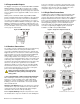
First Digit 9 Event Access Granted User Code Entered A Arming Disarming B Zone is OK Zone is Open Feature Select Programming Second Digit 1 2 3 0 Door 01 Door 02 Door 03 Door 04 Door 05 Door 06 Door 07 Door 08 1 Door 09 Door 10 Door 11 Door 12 Door 13 Door 14 Door 15 Door 16 2 Door 17 Door 18 Door 19 Door 20 Door 21 Door 22 Door 23 Door 24 3 Door 25 Door 26 Door 27 Door 28 Door 29 Door 30 Door 31 Door 32 8 Code 01 Code 02 Code 03 Code 04 Code 05 Code 0
First Digit C D 1 2 3 4 5 6 7 8 0 Zone 01 Zone 02 Zone 03 Zone 04 Zone 05 Zone 06 Zone 07 Zone 08 1 Zone 09 Zone 10 Zone 11 Zone 12 Zone 13 Zone 14 Zone 15 Zone 16 2 Zone 17 Zone 18 Zone 19 Zone 20 Zone 21 Zone 22 Zone 23 Zone 24 3 Zone 25 Zone 26 Zone 27 Zone 28 Zone 29 Zone 30 Zone 31 Zone 32 4 Zone 33 Zone 34 Zone 35 Zone 36 Zone 37 Zone 38 Zone 39 Zone 40 5 Zone 41 Zone 42 Zone 43 Zone 44 Zone 45 Zone 46 Zone 47 Zone 48 Zone Bypass 8 Zone
Table 12: Utility Key Event Generation Table Event Name Using Keyswitch Definition 3 Using Keyswitch Definition 4 Using Keypad Buttons Using Remote Controls Utility Key 1 Keyswitch 001 opens Keyswitch 001 opens [1] + [2] Utility Key 1 ‡ Utility Key 2 Keyswitch 002 opens Keyswitch 001 closes [4] + [5] Utility Key 2 ‡ Utility Key 3 Keyswitch 003 opens Keyswitch 002 opens [7] + [8] Utility Key 3 ‡ Utility Key 4 Keyswitch 004 opens Keyswitch 002 closes [CLEAR] + [0] or [*] + [0] Utility
12.4 Installer Code Lock SECTION [990] Enter 147 into section [990] to lock all programming. When 147 is programmed in section [990], performing a hardware reset as described in section 12.1 on page 35 will not affect the current panel settings. To remove the Installer Lock, enter 000 into section [990]. (Default: Unlocked) 12.5 Partitioning SECTION [500]: OPTIONS [1] TO [4] The Digiplex control panel can provide your system with up to four completely independent partitions.
on the module will begin to flash until the serial number is reentered into section [952] or the appropriate tamper or unlocate switch on the module is pressed. 12.11 Module Programming SECTION [953] All modules connected to the combus are programmed through the control panel. Therefore, if you wish to program a module, enter section [953] to enter Module Programming Mode (see section 3.2 on page 9) and key in the module's serial number.
13 Access Codes The Digiplex control panel supports 95 user access codes, 1 System Master Code, and 1 Installer Code. 13.1 Installer Code SECTION [800] (Default: 000000) The Installer Code is used to enter the control panel's programming mode, which allows you to program all the features, options and commands of the control panel and any modules connected to the combus.
13.5 User Options The User Options define how each user access code can arm or disarm the system. Regardless of these settings, all users can Regular arm (see section 16.1 on page 45) their assigned partitions and all users, except those with the Arm Only option (see section 13.5.4), can disarm an assigned partition. Select one or more of the options described in the following sub-sections for each user access code as shown in Figure 22 on page 38.
Access Control features. This can be used to disable a lost or stolen card without deleting the user access code. Stay Arming with Card Options [4] and [5] ON and Options [6] and [7] OFF = The Access Card can Stay arm the partitions (see section 16.1 on page 45). 13.7.4 Disarm with Access Card Instant Arming with Card SECTIONS [802] TO [896]: ACCESS OPTION SCREEN, OPTION [2] When the partition assigned to an Access Door (see section 14.
14 Access Control Access control is an industry term for a system that monitors and regulates the passage into and out of protected areas. With access control, you can identify who accesses a site and limit the days and times that specific people can enter and exit that site. Each door in the access control system is equipped with a reader, an access control module, a request-for-exit motion detector, a door contact and an electronic door strike.
one partition assigned to the door. An “OR” door will arm or disarm only the partitions that it has in common with the card. Section [340] consists of four screens of eight options each. Each option represents an Access Door. Enable the option corresponding to the door to be set in “OR” Door Access Mode. Options that remain disabled represent doors set in the “AND” Door Access Mode. For example, if option [2] in the Second Screen is enabled in section [340], Door 10 will use the “OR” Door Access Mode.
14.10 Global Access Door Features 14.10.1 Burglar Alarm On Forced Door SECTION [537]: OPTION [5] An Access Door can be assigned to a zone in the Digiplex security system to also be protected by the burglar alarm. If an armed Access Door is forced open (see section 14.2 on page 41), it can send a signal to the control panel to trigger a burglar alarm and to report to the Monitoring Station. The burglar alarm is generated instantly regardless of the zone’s definition (i.e. entry delay is ignored).
15 WinLoad Software The Winload software is not verified by UL. 15.1 Answering Machine Override SECTION [441] When using WinLoad to communicate remotely with an installation site that uses an answering machine or service, the Answering Machine Override must be programmed. Using WinLoad, call the installation site and on the second ring press the [ENTER] key on the keyboard to hang up or hang up manually.
15.9 Call Back Feature SECTION [522]: OPTION [1] For additional security, when a computer using WinLoad attempts to communicate with the control panel, the control panel can hang 16 up and call the computer back to re-verify identification codes and re-establish communication. When the control panel hangs up, WinLoad automatically goes into Wait For Call Mode, ready to answer when the control panel calls back.
3) Press the [DISARM] key. If the users have access to more than one partition, they can press the key corresponding to the desired partition or press [0] to disarm all their assigned partitions. For Grafica keypads: To disarm, users: 1) Enter through a designated entry. The Entry Delay Timer will begin. 2) Enter their [ACCESS CODE]. 3) Using the scroll keys, highlight Disarm and then press the center action key (Ok). If you have access to more than one area, proceed to step 4.
Figure 23: Normal and Confidential Mode Figure 24: LCD Keypad Settings In Normal Mode, the LCD screen displays “Paradox Security” and the time & date, as well as scroll the system, zone and trouble status for every area assigned to the keypad. In Confidential Mode, the LCD screen only displays “Confidential” and the time & date. Depending on how your keypad is programmed, Normal Mode only appears once a button is pressed or a user access code is entered.
Trouble Trouble Description GROUP [7]: ZONE FAULT GROUP [1]: SYSTEM [1] AC Failure [2] Battery Trouble [3] AUX Current Limit [4] Bell Current Limit [5] Bell Absent [6] ROM Check Error Power failure detected. The system is running on the backup battery. The backup battery is disconnected, needs to be recharged or replaced. Devices connected to AUX have exceeded current limits (1.1A). The Auxiliary Output will shutdown until the trouble is corrected. The bell or siren has exceeded current limits (3A).
16.10 Event Record Display The Event Record Display can only be viewed through an LCD or Grafica keypad. The Event Record Display will record the userinitiated actions that occurred in the system as well as any alarms or troubles. For example, when a valid code is entered, the user access code and the action taken (arm, disarm, etc.) is recorded. You have the choice of viewing the events in all the partitions at once or by individual area.
17 Appendix 1: DGP2-641BL/RB Installation Instructions 1.0 INSTALLATION Figure 26 : Connecting the Keypad and Keypad Zone The DGP2-641BL/RB is connected to the control panel's combus in a star and/or daisy chain configuration. This 4-wire combus provides power and two-way communication between the control panel and all modules connected to it.
Figure 29 : Access Control Connections DGP2-641RB DGP2-641RB 2.2 Programming Methods The following methods can be used when programming the keypad: 2.2.1 Feature Select Programming Fused external power supply (recommended) Some sections are programmed by enabling or disabling options. Within the sections, numbers from [1] to [8] represent a specific keypad option. Press the key corresponding to the desired option and the digit will appear in the display. This means the option is enabled.
3.4 Display Entry Delay Timer 3.9 Beep on Exit Delay SECTION [003]: OPTION [3] SECTION [004]: OPTION [2] The Entry Delay Timer will be programmed to provide the user time to enter their User Access Code before the alarm is triggered. The Entry Delay Timer's countdown can be displayed on the LCD screen. The keypad can beep once every second during the Exit Delay Timer. During the final 10 seconds, it will beep more rapidly to provide a final warning before the area is armed.
battery. In some cases adding an external power supply may correct the situation. the PGM Base Time of 1 second or 1 minute ((see section 4.3) above). Default: 5 seconds. 1) 2) 3) 4.6 From Normal Mode press and hold the [0] key. Enter the [INSTALLER CODE] (by default 000000). Press [ACC]. PGM Activation Event SECTIONS [009] TO [012] 4.0 PROGRAMMABLE OUTPUT OPTIONS (DGP2641BL ONLY) The PGM Activation Event determines which event will activate the keypad's on-board PGM output.
unlocked when the REX device detects movement and users on either side of the door will be able to open the door. If this option is off, the door will unlock once the handle is turned only on the REX device’s side. Option [8] OFF = Unlock on REX disabled (default) Option [8] ON = Unlock on REX enabled 5.2.2 Door Unlocked Period SECTION [008] The Door Unlocked Period is the time the door can remain unlatched after access is granted or after a Request for Exit is received.
5.3.4 Door Left Open Pre-Alarm Timer Option [3] OFF = Door Forced Open Alarm is disabled (default) Option [3] ON = Door Forced Open Alarm is enabled SECTION [011] This timer will trigger the Door Left Open Pre-Alarm before the end of the Door Left Open Interval ((see section 5.3.3) above). For example, if 60 seconds is programmed in section [010] and 15 seconds is programmed in section [011], the reader will start beeping after the door has been open for 45 seconds (60 - 15 = 45 seconds).
[STAY] - Insert Space Pressing the [STAY] key inserts a blank space in the current cursor position. [FORCE] - Delete Pressing the [FORCE] key will delete the character or blank space found at the current cursor position. SECTION [006]: General Options 3 for the DGP2-641BL Only Option OFF ON [1] PGM Status U N.O. N N.C. [ARM] - Delete Until the End Pressing the [ARM] key will delete all characters and spaces to the right of the cursor and at the cursor's position.
18 Index Bell terminals ...............................................................2 Bell/siren Output ............................................................2 Bell/Siren Output During Fire Alarm ................................... 13 Sirens ........................................................................2 Troubles ................................................................... 47 A AC Power ......................................................................... 2 Access Alarm .....
Disabled Wireless Transmitter Supervision ..................................... 22 Installer Lock .................................................................... 36 Installer Test Mode ............................................................. 36 Disarm with Access Card ..................................................... 40 Instant Arming .................................................................. 45 Door Access Mode ............................................................
As a 4-wire smoke detector .............................................. 8 Connections ................................................................ 6 PGM Activation Event ................................................... 30 PGM Deactivation Event ............................................... 31 PGM Delay Timers ...................................................... 31 PGM Programming Table ..........................................32–35 PGM Time Base Selection ......................................
19 Warnings FCC Warnings Important Information This equipment complies with Part 68 of the FCC rules subpart D and CS03. Inside the cover of this equipment is a label that contains, among other information, the FCC registration number of this equipment. Notification To Telephone Company Upon request, customer shall notify telephone company of particular line to which the connection will be made and provide the FCC registration number and the ringer equivalence of the protective circuit.
CL3R, CL3P, or substitute cable permitted by the National Electrical Code, ANSI/NFPA 70. 20 Warranty Paradox Security Systems Ltd. (“Seller”) warrants its products to be free from defects in materials and workmanship under normal use for a period of one year. Except as specifically stated herein, all express or implied warranties whatsoever, statutory or otherwise, including without limitation, any implied warranty of merchantability and fitness for a particular purpose, are expressly excluded.
62 Reference & Installation Manual
780 Industriel Blvd., Saint-Eustache (Quebec) J7R 5V3 CANADA Tel.: 450 491-7444 Fax: 450 491-2313 paradox.