DGP-641 LCD Keypad (V1.
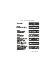
TABLE OF CONTENTS INTRODUCTION ................................................ 3 Specifications ..............................................................3 INSTALLATION ................................................. 4 Connecting the Keypad ..............................................4 Connecting Keypad Zones .........................................4 Programmable Output (PGM) .....................................5 PROGRAMMING ...............................................
Beep on Trouble ....................................................... 12 Keypad Tamper Enable ............................................ 13 PGM PROGRAMMING ....................................14 PGM State ................................................................ 14 PGM Activation Event ............................................... 14 PGM Deactivation Event .......................................... 15 PGM Timed Mode .................................................... 15 PGM Timer ............
1.0 INTRODUCTION Thank you for choosing Paradox® Security Systems. The Digiplex™ Security System is an advanced technology security system that will provide reliable security protection and powerful features that are easy to use. The elegant and user-friendly Digiplex™ LCD Keypad will allow easy access to the security system's functions and information at the touch of a button. Since all programming is accomplished through the keypad, please read this manual carefully. 1.
2.0 INSTALLATION 2.1 CONNECTING THE KEYPAD The Digiplex™ LCD keypads are connected to the control panel's bus in a star and/or daisy chain configuration. This 4-wire communication bus provides power and two-way communication between the control panel and all modules connected to it. Connect the four terminals labeled red, black, green and yellow of each keypad to the corresponding terminals on the control panel as shown in Figure 2.1.
2.3 PROGRAMMABLE OUTPUT (PGM) Each keypad has one on-board PGM. A PGM is a programmable output that toggles to its opposite state (i.e. a normally open PGM will close) when a specific event has occurred in the system (see section 5.2 of this manual). Upon activation, the PGM can provide 50mA to any device connected to it. If the current drawn is to exceed the current limit, a relay should be connected to the PGM as shown in Figure 2.1. Figure 2.
3.0 PROGRAMMING Programming the DGP-641 LCD keypad is simple. Enter the "Module Programming Mode", enter the desired section followed by the required data as shown in Figure 3-1. When programming the keypad, use the DGP-641 LCD Keypad Programming Guide to keep track of which sections were programmed and how. We strongly recommend you read this entire manual before you begin programming. The LCD keypad can also be programmed using the WinLoad Security System Management Software.
Figure 3.
3.2 PROGRAMMING METHODS 3.2.1 Feature Select Programming Program sections [001] to [005] by enabling or disabling options. Within the sections, numbers from [1] to [8] represent a specific keypad option. Press the key corresponding to the desired option and the digit will appear in the display. This means the option is enabled. For example, in Step 6 of Figure 3-1, options [1] and [4] are enabled. Press the key again to remove the digit from the display thereby disabling the option.
4.0 SYSTEM OPTIONS 4.1 PARTITION ASSIGNMENT Section 001: Options [1] to [4] Each keypad in the Digiplex system can be assigned to one or more partitions. In section [001], options [1] to [4] represent partitions 1 through 4 respectively. To assign the keypad to a partition, simply enable the option that corresponds to the desired partition. For example, Step 6 in Figure 3-1 on page 6, would show options 1 and 4 enabled. Therefore, the keypad would be assigned to partitions 1 and 4 only.
4.4 DISPLAY ENTRY DELAY TIMER Section 002: Option [3] Based on the user's needs, an Entry Delay Timer will be programmed to provide the user time to enter their User Access Code before the alarm is triggered. The Entry Delay Timer 's countdown can be displayed on the LCD screen. Option [3] OFF = Will not display the Entry Delay Timer (default) Option [3] ON = LCD screen will display Entry Delay Timer 4.
Section [002]: Option [4] OFF Option [4] ON = Normal Mode (default) = Confidential Mode Option [5] OFF Option [5] ON = LCD screen activated by entering an access code (default) = LCD screen activated by pressing a button Section [006]: = Confidential Mode Timer can be set from 005 to 255 seconds (default: 2 minutes) Figure 4-1: LCD Screen 4.6 MUTING Section 003: Option [1] The keypad can be programmed not to emit audible sounds, including Chimed zones.
4.7 BEEP ON EXIT DELAY Section 003: Option [2] The keypad can beep once every second during the Exit Delay Timer. During the final 10 seconds, it will beep more rapidly to provide a final warning before the area is armed. Option [2] OFF = Exit Delay beep disabled Option [2] ON = Exit Delay beep enabled (default) 4.
The intermittent beep will be re-initialized whenever the trouble condition re-occurs.
5.0 PGM PROGRAMMING 5.1 PGM STATE Section 005: Option [1] The keypad's on-board PGM can be set as normally open or normally closed. When an open PGM is activated, it will close the circuit from ground and enable any devices connected to it. When a closed PGM is activated, it will open the circuit and disable any devices connected to it. When the PGM Activation Event occurs (see section 5.2 of this manual), the PGM will switch to its opposite state (i.e. open to closed or closed to open).
2) Then enter the second digit, which can be any digit from 0 to F depending on the first digit chosen. 3) After entering the second digit, use Feature Select Programming to enable/disable options [1] to [8]. Each option represents a specific event as detailed in the PGM Programming Table on the Digiplex Programming Guide. These keys represent the hexadecimal values from A to F: [STAY] = A [ARM] =C [BYP] = E [FORCE] = B [DISARM] = D [MEM] = F 5.
5.5 PGM TIMER Section 007 If the keypad's on-board PGM is in PGM Timed Mode, the value programmed in section [007] represents how long the PGM will remain in its opposite state (see section 5.1 of this manual) after being activated. To program the timer, enter a 3-digit decimal value (000 to 255) in section [007]. The 3-digit value will be multiplied by the PGM Base Time of 1 second or 1 minute (see section 5.6 of this manual). 5.
6.0 MESSAGE PROGRAMMING Sections 101 to 249 Each section from [101] to [249] contains one message with a maximum of 16 characters. For more details and to record any changes, use the DGP-641 LCD Programming Guide.
[STAY] - Insert Space Pressing the [STAY] key inserts a blank space in the current cursor position. [FORCE] - Delete Pressing the [FORCE] key will delete the character or blank space found at the current cursor position. [ARM] - Delete Until the End Pressing the [ARM] key will delete all characters and spaces to the right of the cursor and at the cursor's position.
Table 2: Special Characters Catalog Digiplex LCD Keypad 19n
Warranty The Seller warrants its products to be free from defects in materials and workmanship under normal use for a period of one year. Except as specifically stated herein, all express or implied warranties whatsoever, statutory or otherwise, including without limitation, any implied warranty of merchantability and fitness for a particular purpose, are expressly excluded.